Toyota Venza: Seat Heater Control
Components
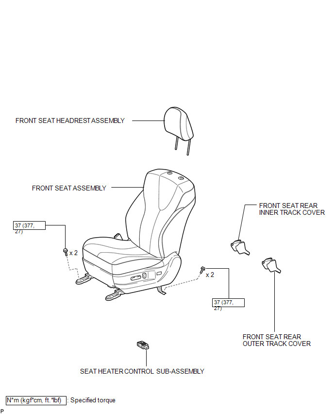
COMPONENTS
ILLUSTRATION
Installation
INSTALLATION
PROCEDURE
1. INSTALL SEAT HEATER CONTROL SUB-ASSEMBLY
|
(a) Engage the clamp and install the seat heater control sub-assembly. |
|
(b) Connect the connector.
2. INSTALL FRONT SEAT ASSEMBLY
.gif)
3. INSTALL FRONT SEAT REAR INNER TRACK COVER
4. INSTALL FRONT SEAT REAR OUTER TRACK COVER
5. INSTALL FRONT SEAT HEADREST ASSEMBLY
6. INSPECT FRONT SEAT ASSEMBLY
7. INSPECT SRS WARNING LIGHT
(See page )
Removal
REMOVAL
PROCEDURE
1. REMOVE FRONT SEAT HEADREST ASSEMBLY
2. REMOVE FRONT SEAT REAR OUTER TRACK COVER
.gif)
3. REMOVE FRONT SEAT REAR INNER TRACK COVER
4. REMOVE FRONT SEAT ASSEMBLY
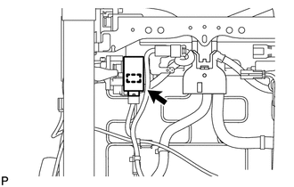
5. REMOVE SEAT HEATER CONTROL SUB-ASSEMBLY
|
(a) Disconnect the connector. |
|
.png)
(b) Disengage the clamp and remove the seat heater control sub-assembly.
 Installation
INSTALLATION
PROCEDURE
1. INSTALL REAR SEAT ASSEMBLY RH
(a) Place the rear seat assembly RH in the cabin.
NOTICE:
Be careful not to damage the vehicle body.
(b) Temporarily install th ...
 Seat Heater Switch
Components
COMPONENTS
ILLUSTRATION
Removal
REMOVAL
PROCEDURE
1. REMOVE UPPER CONSOLE PANEL SUB-ASSEMBLY
2. REMOVE SEAT HEATER SWITCH
(a) Disengage the 2 claws and remove th ...
Other materials about Toyota Venza:
Diagnosis System
DIAGNOSIS SYSTEM
1. DESCRIPTION
(a) Front power seat control system (w/ Memory) data and Diagnostic Trouble Codes
(DTCs) can be read through the Data Link Connector 3 (DLC3) of the vehicle. When
the system seems to be malfunctioning, use the Techstream t ...
Canceling the power back door system (vehicles with power back door)
Turn the main switch to disable the power back door system.
1. Inoperative
2. Operative
The back door cannot be operated even with the wireless remote control or power
back door switch.
A buzzer will sound twice if the power back door switch is pressed ...
Removal
REMOVAL
PROCEDURE
1. PRECAUTION
NOTICE:
After turning the ignition switch off, waiting time may be required before disconnecting
the cable from the negative (-) battery terminal. Therefore, make sure to read the
disconnecting the cable from the negativ ...

0.143