Toyota Venza: Installation
INSTALLATION
PROCEDURE
1. INSTALL DISCHARGE HEADLIGHT BULB
HINT:
Use the same procedure for the RH side and LH side (See page
.gif) ).
).
2. INSTALL LIGHT CONTROL ECU (for LH Side)
|
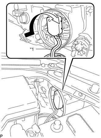
(a) Turn the socket of the light control ECU in the direction indicated by the arrow shown in the illustration to connect it. Text in Illustration
NOTICE:
|
|
(b) Check that the red line on the output harness is not twisted and store the harness in the headlight assembly securely so that the output harness is not pinched.
|
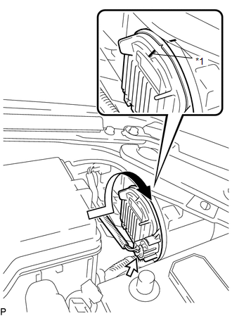
(c) Turn the light control ECU in the direction indicated by the arrow shown in the illustration until the lock marks are aligned to install it. Text in Illustration
NOTICE:
|
|
(d) Connect the connector.
3. INSTALL LIGHT CONTROL ECU (for RH Side)
|
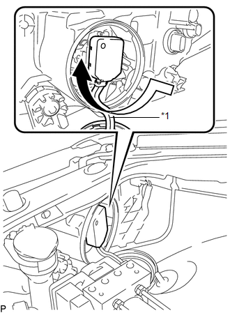
(a) Turn the socket of the light control ECU in the direction indicated by the arrow shown in the illustration to connect it. Text in Illustration
NOTICE:
|
|
(b) Check that the red line on the output harness is not twisted and store the harness in the headlight assembly securely so that the output harness is not pinched.
|
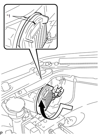
(c) Turn the light control ECU in the direction indicated by the arrow shown in the illustration until the lock marks are aligned to install it. Text in Illustration
NOTICE:
|
|
(d) Connect the connector.
4. INSTALL RADIATOR RESERVE TANK ASSEMBLY (for RH Side)
5. CONNECT CABLE TO NEGATIVE BATTERY TERMINAL
NOTICE:
When disconnecting the cable, some systems need to be initialized after the cable
is reconnected (See page ).
 On-vehicle Inspection
ON-VEHICLE INSPECTION
PROCEDURE
1. INSPECT DISCHARGE HEADLIGHT BULB
NOTICE:
Confirm the following items before replacing a discharge headlight bulb. If a
malfunction is discovered and repaired, ...
 Removal
REMOVAL
CAUTION / NOTICE / HINT
PROCEDURE
1. PRECAUTION
NOTICE:
After turning the ignition switch off, waiting time may be required before disconnecting
the cable from the negative (-) battery ...
Other materials about Toyota Venza:
XM Tuner Malfunction (B15BA)
DESCRIPTION
These DTCs are stored when a malfunction occurs in the stereo component tuner
assembly.
DTC No.
DTC Detection Condition
Trouble Area
B15BA
When either of the following conditions is m ...
Illumination for Panel Switch does not Come on with Tail Switch ON
PROCEDURE
1.
CHECK VEHICLE SIGNAL (OPERATION CHECK)
(a) Enter the "Vehicle Signal Check Mode" screen.
Refer to Check Vehicle Signal in Operation Check (See page
).
...
Speed Signal Circuit
DESCRIPTION
The combination meter assembly receives the vehicle speed signal from this circuit.
The wheel speed sensors produce an output that varies according to the vehicle speed.
The wheel speed sensor output is received by the skid control ECU which u ...

0.1469