Toyota Venza: Removal
REMOVAL
CAUTION / NOTICE / HINT
HINT:
- Use the same procedure for the RH side and LH side.
- The procedure listed below is for the LH side.
PROCEDURE
1. REMOVE REAR WHEEL
2. SEPARATE REAR FLEXIBLE HOSE
.gif)
3. SEPARATE REAR DISC BRAKE CALIPER ASSEMBLY
4. REMOVE REAR DISC
5. SEPARATE REAR SPEED SENSOR WIRE
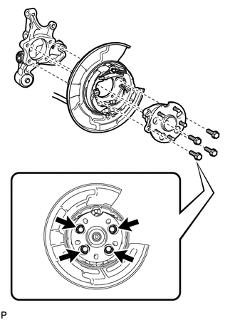
6. REMOVE REAR AXLE HUB AND BEARING ASSEMBLY
|
(a) Remove the 4 bolts and the rear axle hub and bearing assembly. NOTICE: Use wire or an equivalent tool to keep the parking brake assembly from hanging down by the parking brake cable assembly. |
|
 On-vehicle Inspection
ON-VEHICLE INSPECTION
CAUTION / NOTICE / HINT
HINT:
Use the same procedure for the RH side and LH side.
The procedure listed below is for the LH side.
PROCEDURE
1. REMOVE REAR W ...
 Installation
INSTALLATION
CAUTION / NOTICE / HINT
HINT:
Use the same procedure for the RH side and LH side.
The procedure listed below is for the LH side.
PROCEDURE
1. INSTALL REAR AXLE HUB ...
Other materials about Toyota Venza:
Transmission Range Sensor Circuit Malfunction (PRNDL Input) (P0705)
DESCRIPTION
The park/neutral position switch detects the shift lever position and sends signals
to the TCM.
DTC No.
DTC Detection Condition
Trouble Area
P0705
(A) Any 2 or more signals of the fol ...
Inspection
INSPECTION
PROCEDURE
1. INSPECT FRONT NO. 2 SPEAKER ASSEMBLY (for 6 Speakers)
(a) With the speaker installed, check that there is no looseness or other abnormalities.
(b) Check that there is no foreign matter in the speaker, no tears on the speaker
cone ...
Correct driving posture
Drive with a good posture as follows:
1. Sit upright and well back in the seat.
2. Adjust the position of the seat forward or backward to ensure the pedals can
be reached and easily depressed to the extent required. 3. Adjust the seatback so
that the c ...

0.1284