Toyota Venza: Power Back Door Main Switch
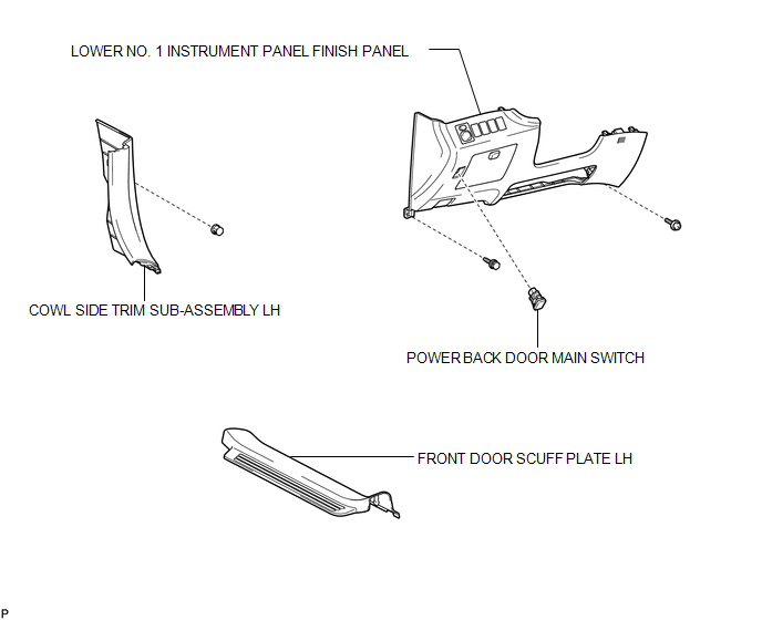
Components
COMPONENTS
ILLUSTRATION
Inspection
INSPECTION
PROCEDURE
1. INSPECT POWER BACK DOOR MAIN SWITCH
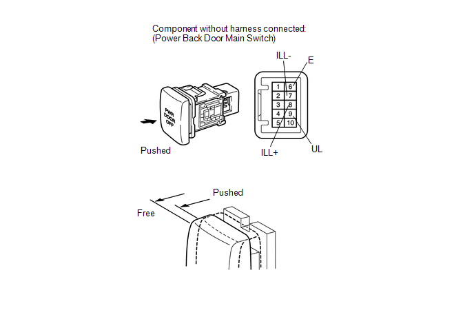
(a) Check that the switch function.
(1) Measure the resistance according to the value(s) in the table below.
Standard Resistance:
|
Tester Connection |
Switch Condition |
Specified Condition |
|---|---|---|
|
6 (E) - 9 (UL) |
Free |
Below 1 Ω |
|
6 (E) - 9 (UL) |
Pushed |
10 kΩ or higher |
If the result is not as specified, replace the switch.
(b) Check that the switch illuminates.
(1) Apply battery voltage to the power back door main switch and check that the switch illuminates.
OK:
|
Measurement Condition |
Specified Condition |
|---|---|
|
Battery positive (+) → 8 (ILL+) Battery negative (-) → 7 (ILL-) |
Illuminates |
If the result is not as specified, replace the switch.
Removal
REMOVAL
PROCEDURE
1. REMOVE FRONT DOOR SCUFF PLATE LH
.gif)
2. REMOVE COWL SIDE TRIM SUB-ASSEMBLY LH
3. REMOVE LOWER NO. 1 INSTRUMENT PANEL FINISH PANEL
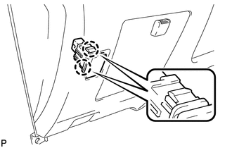
4. REMOVE POWER BACK DOOR MAIN SWITCH
|
(a) Disengage the 2 claws and remove the power back door main switch. |
|
Installation
INSTALLATION
PROCEDURE
1. INSTALL POWER BACK DOOR MAIN SWITCH
|
(a) Engage the 2 claws and install the power back door main switch. |
|
.png)
2. INSTALL LOWER NO. 1 INSTRUMENT PANEL FINISH PANEL
.gif)
3. INSTALL COWL SIDE TRIM SUB-ASSEMBLY LH
4. INSTALL FRONT DOOR SCUFF PLATE LH
 Installation
INSTALLATION
PROCEDURE
1. INSTALL POWER BACK DOOR UNIT ASSEMBLY
(a) Install the power back door unit with the 4 bolts.
Torque:
13 N·m {133 kgf·cm, 10 ft·lbf}
...

Other materials about Toyota Venza:
XM Tuner Antenna Disconnected (B15FE,B15FF)
DESCRIPTION
These DTCs are stored when a malfunction occurs in the roof antenna assembly
which is connected to the stereo component tuner assembly.
DTC No.
DTC Detection Condition
Trouble Area
B15FE
...
Calibration
CALIBRATION
1. SELECT COMPASS DISPLAY MODE
(a) The AUTO switch allows selection of the compass display.
2. PERFORM CALIBRATION
(a) Because each vehicle has its own magnetic field, calibration should be performed.
The calibration function is used to compe ...
Automatic High Beam Mirror (B124A)
DESCRIPTION
The DTC is stored when the main body ECU (driver side junction block assembly)
detects malfunctions in the inner rear view mirror assembly.
DTC No.
DTC Detection Condition
Trouble Area
B124A
...

0.1859