Toyota Venza: Installation
INSTALLATION
PROCEDURE
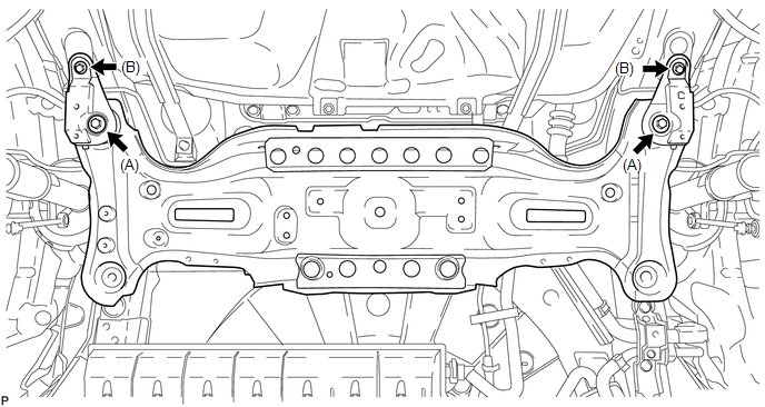
1. INSTALL STUD BOLT (for LH Side)
|
(a) Install the stud bolt. Torque: 17 N·m {173 kgf·cm, 13 ft·lbf} |
|
.png)
2. INSTALL STUD BOLT (for RH Side)
HINT:
Perform the same procedure as the LH side.
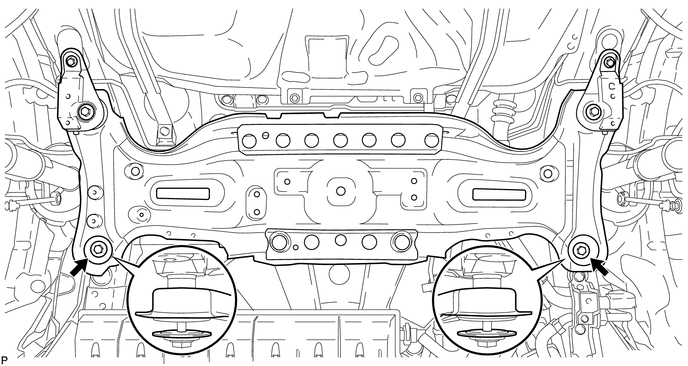
3. INSTALL HOLE PLUG
|
(a) Install the hole plugs to the rear suspension member sub-assembly. HINT: There are 2 sizes of the hole plugs. |
|
.png)
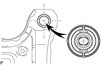
4. INSTALL REAR SUSPENSION MEMBER BODY MOUNTING FRONT CUSHION LH
|
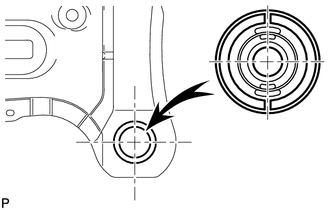
(a) Temporarily install a new rear suspension member body mounting front cushion LH to the position shown in the illustration. |
|
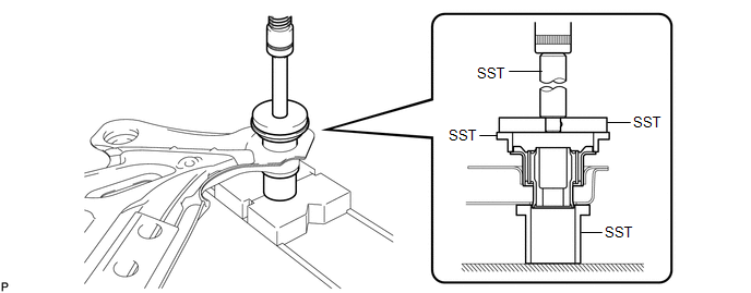
(b) Using SST and a press, install the rear suspension member body mounting front cushion LH to the rear suspension member sub-assembly.
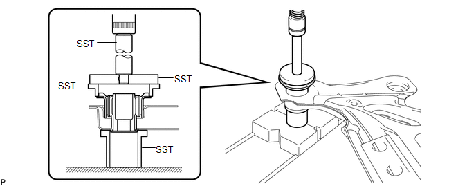
SST: 09502-12010
SST: 09515-30010
SST: 09950-60020
09951-00890
SST: 09950-70010
09951-07100
HINT:
Slowly press in the mounting cushion.
|
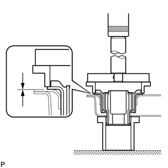
(c) While observing from the side, press in the rear suspension member body mounting front cushion LH until there is no clearance between the rear suspension member body mounting front cushion LH and the rear suspension member sub-assembly as shown in the illustration. NOTICE: Do not press the rear suspension member excessively, or it will easily deform. |
|
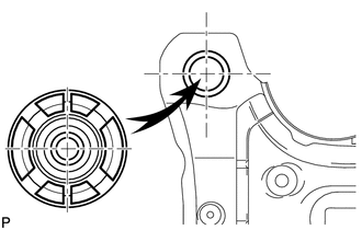
5. INSTALL REAR SUSPENSION MEMBER BODY MOUNTING FRONT CUSHION RH
|
(a) Temporarily install a new rear suspension member body mounting front cushion RH to the position shown in the illustration. |
|
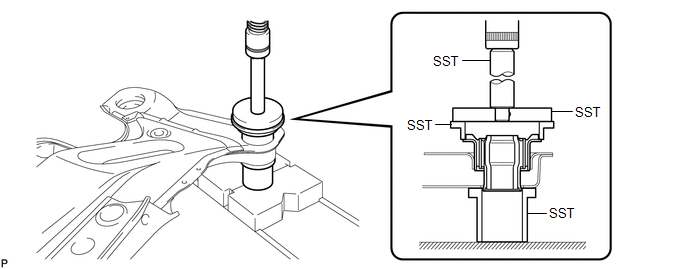
(b) Using SST and a press, install the rear suspension member body mounting front cushion RH to the rear suspension member sub-assembly.
SST: 09502-12010
SST: 09515-30010
SST: 09950-60020
09951-00890
SST: 09950-70010
09951-07100
HINT:
Slowly press in the mounting cushion.
|
(c) While observing from the side, press in the rear suspension member body mounting front cushion RH until there is no clearance between the rear suspension member body mounting front cushion RH and the rear suspension member sub-assembly as shown in the illustration. NOTICE: Do not press the rear suspension member excessively, or it will easily deform. |
|
6. INSTALL REAR SUSPENSION MEMBER BODY MOUNTING REAR CUSHION (for LH Side)
|
(a) Temporarily install a new rear suspension member body mounting rear cushion (LH side) to the position shown in the illustration. |
|
(b) Using SST and a press, install the rear suspension member body mounting rear cushion (LH side) to the rear suspension member sub-assembly.
SST: 09502-12010
SST: 09515-30010
SST: 09950-60020
09951-00890
SST: 09950-70010
09951-07100
HINT:
Slowly press in the mounting cushion.
|
(c) While observing from the side, press in the rear suspension member body mounting rear cushion (LH side) until there is no clearance between the rear suspension member body mounting rear cushion (LH side) and the rear suspension member sub-assembly as shown in the illustration. NOTICE: Do not press the rear suspension member excessively, or it will easily deform. |
|
7. INSTALL REAR SUSPENSION MEMBER BODY MOUNTING REAR CUSHION (for RH Side)
HINT:
Perform the same procedure as the LH side.
8. INSTALL REAR SUSPENSION MEMBER
|
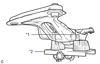
(a) Support the rear suspension member using a jack and 2 wooden blocks as shown in the illustration. Text in Illustration
NOTICE: Make sure to secure the rear suspension member to prevent it from dropping. HINT: Use properly sized wooden blocks to keep the jack and suspension member level. |
|
(b) Raise the rear suspension member using a jack with wooden blocks.
NOTICE:
When raising the rear suspension member, be careful not to damage the vehicle body or other components installed on the vehicle.
(c) Install the rear suspension member and rear lower suspension member stopper LH and rear lower suspension member stopper RH with the 4 nuts.
Torque:
Nut A :
55 N·m {561 kgf·cm, 41 ft·lbf}
Nut B :
38 N·m {387 kgf·cm, 28 ft·lbf}
(d) Install the rear suspension member and rear lower suspension member stoppers with the 2 bolts.
Torque:
55 N·m {561 kgf·cm, 41 ft·lbf}
NOTICE:
Be sure to install the rear suspension member with the rear lower suspension member stoppers in the correct direction shown in the illustration.
9. TEMPORARILY INSTALL REAR NO. 1 SUSPENSION ARM ASSEMBLY LH
.gif)
10. TEMPORARILY INSTALL REAR NO. 1 SUSPENSION ARM ASSEMBLY RH
11. TEMPORARILY INSTALL REAR NO. 2 SUSPENSION ARM ASSEMBLY LH
12. TEMPORARILY INSTALL REAR NO. 2 SUSPENSION ARM ASSEMBLY RH
13. INSTALL LOWER NO. 1 EXHAUST PIPE SUPPORT BRACKET
|
(a) Install the lower No. 1 exhaust pipe support bracket with the 2 bolts. Torque: 33 N·m {337 kgf·cm, 24 ft·lbf} |
|
.png)
14. INSTALL CENTER EXHAUST PIPE ASSEMBLY
(a) Install the center exhaust pipe assembly.
HINT:
Refer to the instructions for Installation of the exhaust pipe (See page
for 2GR-FE,
for 1AR-FE).
15. INSPECT FOR EXHAUST GAS LEAK
16. STABILIZE SUSPENSION
17. FULLY TIGHTEN REAR NO. 1 SUSPENSION ARM ASSEMBLY LH
18. FULLY TIGHTEN REAR NO. 1 SUSPENSION ARM ASSEMBLY RH
19. FULLY TIGHTEN REAR NO. 2 SUSPENSION ARM ASSEMBLY LH
20. FULLY TIGHTEN REAR NO. 2 SUSPENSION ARM ASSEMBLY RH
21. INSTALL REAR HEIGHT CONTROL SENSOR SUB-ASSEMBLY (w/ HID Headlight System)
22. INSTALL REAR STABILIZER BAR
23. INSTALL REAR STABILIZER LINK ASSEMBLY LH
24. INSTALL REAR STABILIZER LINK ASSEMBLY RH
25. INSTALL REAR WHEELS
Torque:
103 N·m {1050 kgf·cm, 76 ft·lbf}
26. INSPECT AND ADJUST REAR WHEEL ALIGNMENT
(a) Inspect and adjust the rear wheel alignment (See page
).
27. HEIGHT CONTROL SENSOR SIGNAL INITIALIZATION (w/ HID Headlight System)
(a) Initialize the height control sensor signal (See page
).
28. INSPECT AND ADJUST HEADLIGHT AIMING (w/ HID Headlight System)
(a) Inspect and adjust the headlight aiming (See page
).
 Removal
REMOVAL
PROCEDURE
1. REMOVE REAR WHEELS
2. REMOVE CENTER EXHAUST PIPE ASSEMBLY
(a) Remove the center exhaust pipe assembly.
HINT:
Refer to the instructions for Removal of the exhaust pipe (See p ...

Other materials about Toyota Venza:
Mechanical System Tests
MECHANICAL SYSTEM TESTS
1. STALL SPEED TEST
HINT:
This test is to check the overall performance of the engine and transaxle.
CAUTION:
Driving test should be done on a paved surface (a surface that is not
slippery).
To ensure safety, perfor ...
Washer Motor(for Front Side)
Components
COMPONENTS
ILLUSTRATION
Removal
REMOVAL
PROCEDURE
1. REMOVE FRONT WHEEL RH
2. REMOVE FRONT FENDER OUTSIDE MOULDING RH
HINT:
Use the same procedure for the RH side and LH side (See page
).
3. REMOVE FRONT FENDER LINER RH
...
Diagnostic Trouble Code Chart
DIAGNOSTIC TROUBLE CODE CHART
If a trouble code is displayed during the DTC check, check the parts listed for
that code in the table below and proceed to the appropriate page.
HINT:
The steering lock ECU does not store DTCs regarding the past problems.
S ...

0.1142