Toyota Venza: Communication Malfunction between ECUs Connected by LIN (B2785)
DESCRIPTION
This DTC is stored when LIN communication from the certification ECU stops for a certain amount of time.
|
DTC No. |
DTC Detection Condition |
Trouble Area |
|---|---|---|
|
B2785 |
|
|
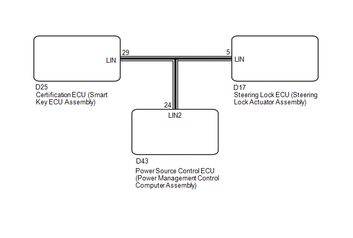
WIRING DIAGRAM
CAUTION / NOTICE / HINT
NOTICE:
- If the certification ECU (smart key ECU assembly) is replaced, register the key.
- If the steering lock ECU (steering lock actuator assembly) is replaced, register the ECU code.
- When using the Techstream to troubleshoot with the ignition switch off:
Connect the Techstream to the DLC3, and turn the courtesy switch on and off at 1.5-second intervals until communication between the Techstream and vehicle begins.
PROCEDURE
|
1. |
CHECK HARNESS AND CONNECTOR (CERTIFICATION ECU - EACH ECU) |
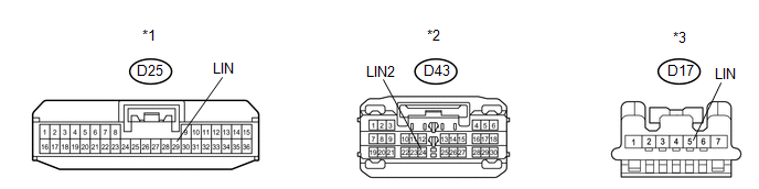
(a) Disconnect the D25, D43 and D17 ECU connectors.
 Text in Illustration
|
*1 |
Front view of wire harness connector (to Certification ECU (Smart Key ECU Assembly)) |
*2 |
Front view of wire harness connector (to Power Management Control ECU) |
|
*3 |
Front view of wire harness connector (to Steering Lock ECU (Steering Lock Actuator Assembly)) |
- |
- |
(b) Measure the resistance and voltage according to the value(s) in the table below.
Standard Resistance:
|
Tester Connection |
Condition |
Specified Condition |
|---|---|---|
|
D25-29 (LIN) - D17-5 (LIN) |
Always |
Below 1 Ω |
|
D25-29 (LIN) - D43-24 (LIN2) |
Always |
Below 1 Ω |
|
D25-29 (LIN) - Body ground |
Always |
10 kΩ or higher |
Standard Voltage:
|
Tester Connection |
Condition |
Specified Condition |
|---|---|---|
|
D25-29 (LIN) - Body ground |
Always |
Below 1 V |
| NG | .gif) |
REPAIR OR REPLACE HARNESS OR CONNECTOR |
|
.gif)
|
2. |
CHECK DTC OUTPUT (STEERING LOCK ECU (STEERING LOCK ACTUATOR ASSEMBLY)) |
(a) Reconnect the D25 and D43 ECU connectors.
(b) Clear the DTC (See page .gif) ).
).
(c) Recheck for DTCs.
|
Result |
Proceed to |
|---|---|
|
DTC B2785 is output |
A |
|
DTC B2785 is not output |
B |
| B | |
REPLACE STEERING LOCK ECU (STEERING LOCK ACTUATOR ASSEMBLY) |
|
|
3. |
CHECK DTC OUTPUT (POWER MANAGEMENT CONTROL ECU) |
(a) Reconnect the D17 ECU connector.
(b) Disconnect the D43 ECU connector.
(c) Clear the DTC (See page ).
(d) Recheck for DTCs.
|
Result |
Proceed to |
|---|---|
|
DTC B2785 is output |
A |
|
DTC B2785 is not output |
B |
| A | |
REPLACE CERTIFICATION ECU (SMART KEY ECU ASSEMBLY) |
| B | |
REPLACE POWER MANAGEMENT CONTROL ECU |
 Lost Communication with Automatic High Beam Sensor (B2432)
DESCRIPTION
Refer to DTC B2432 (Lighting system) (See page
).
DTC No.
DTC Detection Condition
Trouble Area
B2432
Malfunction in LIN com ...
 Rear Door LH ECU Communication Stop (B2324)
DESCRIPTION
This DTC is stored when LIN communication between the power window regulator
motor assembly (for rear LH side) and main body ECU (driver side junction block
assembly) stops for more t ...
Other materials about Toyota Venza:
Terminals Of Ecm
TERMINALS OF ECM
1. CHECK ECM
Terminal No. (Symbol)
Wiring Color
Terminal Description
Condition
Specified Condition
A49-7 (TC) - B58-104 (E1)
V - BR
Terminal TC o ...
Precaution
PRECAUTION
1. IGNITION SWITCH EXPRESSIONS
HINT:
The type of ignition switch used on this model differs according to the specifications
of the vehicle. The expressions listed in the table below are used in this section.
Expression
Sw ...
Removal
REMOVAL
PROCEDURE
1. REMOVE YAW RATE AND ACCELERATION SENSOR
HINT:
Refer to the instructions for Removal of the yaw rate and acceleration sensor
(See page ).
2. REMOVE REAR NO. 2 AIR DUCT
3. REMOVE REAR NO. 1 AIR DUCT
4. REMOVE FRONT NO. 2 FLOO ...

0.1603