
Toyota Venza: Inspection
INSPECTION
PROCEDURE
1. INSPECT CHARCOAL CANISTER ASSEMBLY
(a) Visually check the charcoal canister assembly.
|
(1) Visually check the charcoal canister assembly for cracks or damage. If cracks or damage are found, replace the charcoal canister assembly. |
|
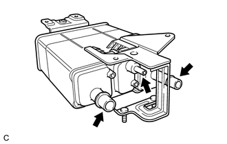
(b) Check canister operation.
|
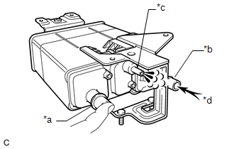
(1) With the purge line port closed, blow 0.5 kPa (0.005 kgf/cm2, 0.1 psi) of air into the vent line port, and check that air flows from the air line port. Text in Illustration
If the result is not as specified, replace the charcoal canister assembly. |
|
|
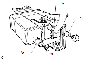
(2) With the vent line port closed, blow 0.5 kPa (0.005 kgf/cm2, 0.1 psi) of air into the air line port, and check that air flows from the purge line port. Text in Illustration
If the result is not as specified, replace the charcoal canister assembly. |
|
(c) Check for air leaks.
|
(1) Connect a pressure gauge to the vent line port of the charcoal canister assembly. Text in Illustration
|
|
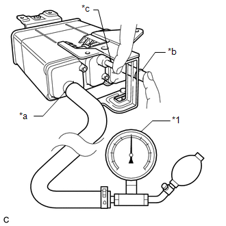
(2) With the purge line port and the air line port closed, apply 20 kPa (150 mmHg, 5.91 in.Hg) of pressurized air into the vent line port, then confirm that pressure is retained for 1 minute.
If the result is not as specified, replace the charcoal canister assembly.
(d) Check the charcoal canister leak detection pump sub-assembly.
|
(1) Connect a positive (+) lead from the battery to terminal 5 and a negative (-) lead to terminal 1. |
|
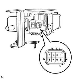
(2) Check that a clicking sound is heard from the charcoal canister leak detection pump sub-assembly.
If the result is not as specified, replace the charcoal canister leak detection pump sub-assembly.
 Removal
REMOVAL
PROCEDURE
1. REMOVE NO. 1 FLOOR UNDER COVER
(a) Disengage the 4 nuts and clip, and remove the No. 1 floor under cover.
Text in Illustration
Nut (attached to under cov ...
 Installation
INSTALLATION
PROCEDURE
1. INSTALL CHARCOAL CANISTER LEAK DETECTION PUMP SUB-ASSEMBLY
(a) Engage the 2 claws to install a new charcoal canister leak detection
pump sub-assembly to the ...
Other materials about Toyota Venza:
System Description
SYSTEM DESCRIPTION
1. PUSH-BUTTON START DESCRIPTION
(a) The push-button start uses a push-type engine switch, which the driver can
operate by merely carrying the electrical key. This system consists primarily of
the power management control ECU, engine s ...
Reassembly
REASSEMBLY
PROCEDURE
1. INSTALL SHIFT SOLENOID VALVE SL4
(a) Coat the shift solenoid valve SL4 and bolt with ATF.
Text in Illustration
*1
Lock Plate
*2
Solenoid V ...
Removal
REMOVAL
CAUTION / NOTICE / HINT
HINT:
When installing new name plates and emblem, heat the vehicle body, name plates
and emblem using a heat light.
Heating Temperature
Item
Temperature
Vehicle Body
40 to ...

0.1306