Toyota Venza: Inspection
INSPECTION
PROCEDURE
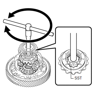
1. INSPECT FRONT DIFFERENTIAL CASE
|
(a) Using SST, rotate the front differential side gear as shown in the illustration. SST: 09528-52010 09528-05030 Standard: The front differential side gear does not lock when rotated in either direction.
|
|
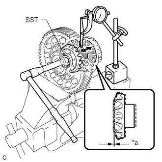
2. INSPECT FRONT DIFFERENTIAL SIDE GEAR THRUST AMOUNT
(a) Secure the front differential case in a vise between aluminum plates.
NOTICE:
Do not overtighten the vise.
|
(b) Using SST and a dial indicator, measure the front differential side gear thrust amount. Text in Illustration
SST: 09528-52010 09528-05030 Front Differential Side Gear Thrust Amount: 0.08 mm (0.00315 in.) or less HINT:
If the result is not as specified, replace the 2 front differential side gears, 2 front differential pinions and 2 conical springs. |
|
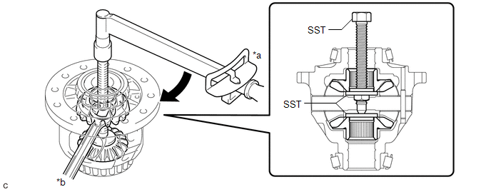
3. INSPECT FRONT DIFFERENTIAL PINION BACKLASH
(a) Install SST as shown in the illustration and tighten it.
 Text in Illustration
|
*a |
Turn |
*b |
Hold |
SST: 09528-52010
09528-05010
09953-05010
Torque:
10 N·m {102 kgf·cm, 7 ft·lbf}
(b) Secure the front differential case in a vise between aluminum plates.
NOTICE:
Do not overtighten the vise.
|
(c) Install the front No. 1 differential pinion shaft to the front differential pinion as shown in the illustration. Text in Illustration
|
|
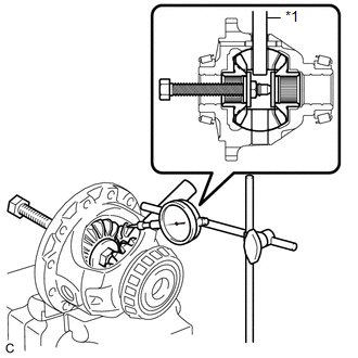
(d) Using a dial indicator, measure the front differential pinion backlash.
Standard Backlash:
0.15 mm (0.00591 in.) or less
HINT:
Select front No. 1 differential side gear thrust washers of the same thickness for both the right and left side.
If the backlash is not as specified, replace the front No. 1 differential side gear thrust washers with washers of a different thickness. Use the table below to select front No. 1 differential side gear thrust washers which will ensure that the backlash is within the specification.
Front No. 1 Differential Side Gear Thrust Washer Thickness:|
Part No. |
Thickness (mm (in.)) |
|---|---|
|
41361-06010 |
1.50 (0.0591) |
|
41361-06020 |
1.55 (0.0610) |
|
41361-06030 |
1.60 (0.0630) |
|
41361-06040 |
1.65 (0.0650) |
|
41361-06050 |
1.70 (0.0669) |
|
41361-06060 |
1.75 (0.0689) |
|
41361-06070 |
1.80 (0.0709) |
|
41361-06080 |
1.85 (0.0728) |
|
41361-06090 |
1.90 (0.0748) |
4. INSPECT FRONT DIFFERENTIAL PINION THRUST WASHER
|
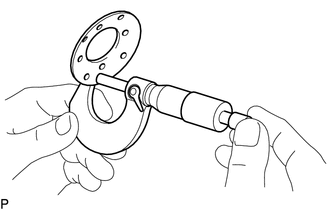
(a) Using a micrometer, measure the thickness of the front differential pinion thrust washer. Minimum Thickness: 0.54 mm (0.0213 in.) HINT: Measure the most worn portion of the front differential pinion thrust washer. If the thickness is less than the minimum, replace the front differential pinion thrust washer. |
|
5. INSPECT FRONT NO. 1 DIFFERENTIAL PINION SHAFT
|
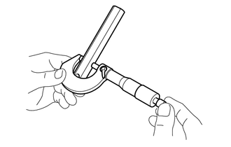
(a) Using a micrometer, measure the outer diameter of the front No. 1 differential pinion shaft. Minimum Outer Diameter: 20.499 mm (0.807 in.) HINT: Measure the most worn portion of the front No. 1 differential pinion shaft. If the outer diameter is less than the minimum, replace the front No. 1 differential pinion shaft. |
|
 Disassembly
DISASSEMBLY
PROCEDURE
1. REMOVE FRONT TRANSAXLE CASE OIL SEAL
(a) Using SST, remove the front transaxle case oil seal from the transaxle
housing.
SST: 09308-00010
...
 Reassembly
REASSEMBLY
PROCEDURE
1. INSTALL FRONT DIFFERENTIAL CASE REAR TAPERED ROLLER BEARING
(a) Using SST and a press, install a new front differential case rear
tapered roller bearing (inne ...
Other materials about Toyota Venza:
Calculation formula for your vehicle
1. Cargo capacity
2. Total load capacity (vehicle capacity weight)
When 2 people with the combined weight of A lb. (kg) are riding in your vehicle,
which has a total load capacity (vehicle capacity weight) of B lb. (kg), the available
amount of cargo a ...
LVDS Signal Malfunction (from Extension Module) (B1532)
DESCRIPTION
The stereo component tuner assembly and the navigation receiver assembly are
connected by the LVDS communication line.
This DTC is stored when an LVDS communication error occurs between the stereo
component tuner assembly and the navigation r ...
Speaker Output Short (B15C3)
DESCRIPTION
This DTC is stored when a malfunction occurs in the speakers.
DTC No.
DTC Detection Condition
Trouble Area
B15C3
A short is detected in the speaker output circuit
...

0.1598