Toyota Venza: Disassembly
DISASSEMBLY
PROCEDURE
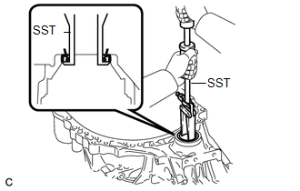
1. REMOVE FRONT TRANSAXLE CASE OIL SEAL
|
(a) Using SST, remove the front transaxle case oil seal from the transaxle housing. SST: 09308-00010 |
|
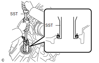
2. REMOVE TRANSAXLE CASE OIL SEAL
|
(a) Using SST, remove the transaxle case oil seal from the transaxle case sub-assembly. SST: 09308-00010 |
|
3. INSPECT FRONT DIFFERENTIAL CASE
.gif)
4. INSPECT FRONT DIFFERENTIAL SIDE GEAR THRUST AMOUNT
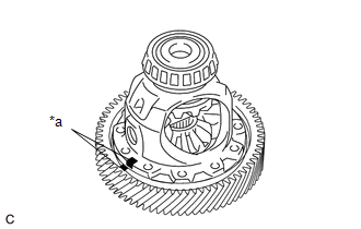
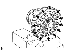
5. REMOVE FRONT DIFFERENTIAL RING GEAR
|
(a) Put matchmarks on the front differential ring gear and front differential case. Text in Illustration
|
|
|
(b) Remove the 12 bolts from the front differential ring gear. |
|
|
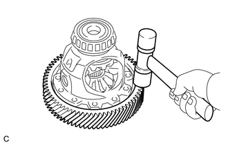
(c) Using a plastic hammer, tap on the front differential ring gear to remove it from the front differential case. |
|
6. REMOVE FRONT DIFFERENTIAL PINION SHAFT STRAIGHT PIN
(a) Secure the front differential case in a vise between aluminum plates.
NOTICE:
Do not overtighten the vise.
|
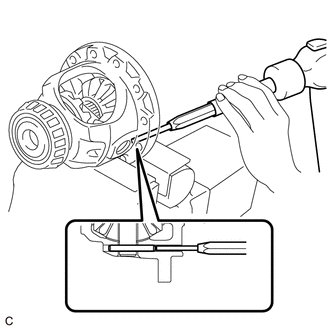
(b) Using a 5 mm pin punch and a hammer, remove the front differential pinion shaft straight pin from the front differential case. |
|
7. REMOVE FRONT NO. 1 DIFFERENTIAL PINION SHAFT
|
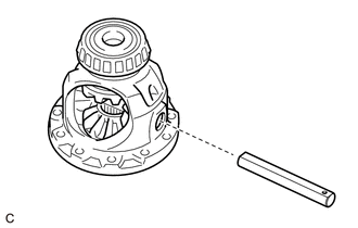
(a) Remove the front No. 1 differential pinion shaft from the front differential case. |
|
8. INSPECT FRONT DIFFERENTIAL PINION BACKLASH
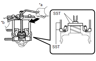
9. REMOVE FRONT DIFFERENTIAL SIDE GEAR
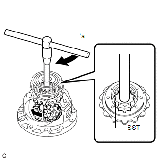
(a) Install SST as shown in the illustration and tighten it.
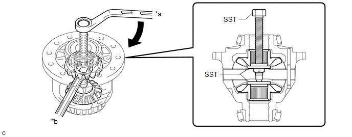 Text in Illustration
|
*a |
Turn |
*b |
Hold |
SST: 09528-52010
09528-05010
09953-05010
NOTICE:
Do not overtighten SST, as doing so will damage the front differential side gears, conical springs, front No. 1 differential side gear thrust washers and front differential case.
HINT:
- Tighten SST until there is clearance between the front differential pinions and front differential side gears.
- When removing the front differential pinions, do not overtighten SST, as it is necessary to rotate the front differential side gears.
|
(b) Install SST as shown in the illustration, rotate the front differential side gear, and then remove the 2 front differential pinions and 2 front differential pinion thrust washers from the front differential case. Text in Illustration
SST: 09528-52010 09528-05030 NOTICE: Do not drop the front differential pinion and front differential pinion thrust washer. |
|
|
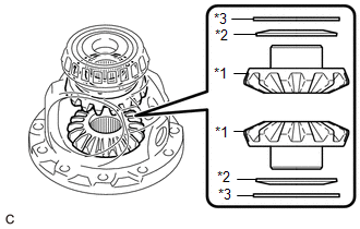
(c) Remove SST from the front differential case, and then remove the 2 front differential side gears, 2 front No. 1 differential side gear thrust washers and 2 conical springs from the front differential case. Text in Illustration
NOTICE: Do not drop the front differential side gear, front No. 1 differential side gear thrust washer or conical spring. |
|
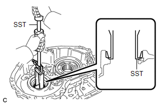
10. REMOVE FRONT DIFFERENTIAL CASE FRONT TAPERED ROLLER BEARING
|
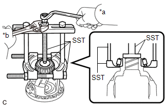
(a) Using SST, remove the front differential case front tapered roller bearing (inner race) from the front differential case. Text in Illustration
SST: 09950-00020 SST: 09950-00030 SST: 09950-40011 09957-04010 SST: 09950-60010 09951-00480 |
|
|
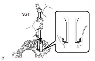
(b) Using SST, remove the front differential case front tapered roller bearing (outer race) and shim from the transaxle housing. SST: 09308-00010 |
|
11. REMOVE FRONT DIFFERENTIAL CASE REAR TAPERED ROLLER BEARING
|
(a) Using SST, remove the front differential case rear tapered roller bearing (inner race) from the front differential case. Text in Illustration
SST: 09950-00020 SST: 09950-00030 SST: 09950-40011 09957-04010 SST: 09950-60010 09951-00480 |
|
|
(b) Using SST, remove the front differential case rear tapered roller bearing (outer race) from the transaxle case sub-assembly. SST: 09308-00010 |
|
 Components
COMPONENTS
ILLUSTRATION
ILLUSTRATION
...
 Inspection
INSPECTION
PROCEDURE
1. INSPECT FRONT DIFFERENTIAL CASE
(a) Using SST, rotate the front differential side gear as shown in the
illustration.
SST: 09528-52010
09528-05030
Sta ...
Other materials about Toyota Venza:
General Information
GENERAL INFORMATION
A large number of ECU controlled systems are used in this vehicle. In
general, ECU controlled systems are considered to be very intricate, requiring
a high level of technical knowledge to troubleshoot. However, most problem ...
Fail-safe Chart
FAIL-SAFE CHART
1. POWER WINDOW OPERATION IN FAIL-SAFE MODE
HINT:
If the pulse sensor built into the power window regulator motor malfunctions,
the power window control system enters fail-safe mode.
(a) The power window control system prohibits the follo ...
Garage Door Opener Switch
Components
COMPONENTS
ILLUSTRATION
Removal
REMOVAL
PROCEDURE
1. REMOVE ROOF CONSOLE BOX ASSEMBLY (GARAGE DOOR OPENER SWITCH)
(a) Using a moulding remover, disengage the 2 claws and 2 clips.
Text in Illustration
*1 ...

0.1472