Toyota Venza: Mass or Volume Air Flow Circuit Low Input (P0102,P0103)
DESCRIPTION
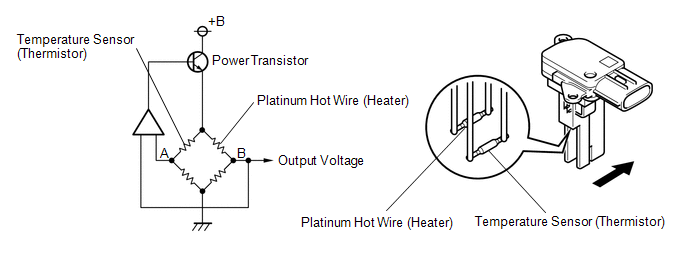
The mass air flow meter is a sensor that measures the amount of air flowing through the throttle valve. The ECM uses this information to determine the fuel injection time and to provide the appropriate air-fuel ratio.
Inside the mass air flow meter, there is a heated platinum wire which is exposed to the flow of intake air. By applying a specific electrical current to the wire, the ECM heats it to a given temperature. The flow of incoming air cools both the wire and an internal thermistor, affecting their resistance. To maintain a constant current value, the ECM varies the voltage applied to the wire and internal thermistor. The voltage level is proportional to the airflow through the sensor, and the ECM uses it to calculate the intake air volume.
The circuit is constructed so that the platinum hot wire and the temperature sensor create a bridge circuit, and the power transistor is controlled so that the potentials of A and B remain equal to maintain the predetermined temperature.
HINT:
When any of these DTCs is stored, the ECM enters fail-safe mode. During fail-safe mode, the ignition timing is calculated by the ECM, according to the engine speed and throttle valve position. Fail-safe mode continues until a pass condition is detected.
|
DTC No. |
DTC Detection Condition |
Trouble Area |
|---|---|---|
|
P0102 |
The mass air flow meter voltage is less than 0.2 V for 3 seconds. (1 trip detection logic: Engine speed is less than 4000 rpm) (2 trip detection logic: Engine speed is 4000 rpm or more) |
|
|
P0103 |
The mass air flow meter voltage is more than 4.9 V for 3 seconds. (1 trip detection logic: Engine speed is less than 4000 rpm) (2 trip detection logic: Engine speed is 4000 rpm or more) |
|
HINT:
When any of these DTCs are output, check the air-flow rate using the Techstream. Enter the following menus: Powertrain / Engine / Data List / MAF.
|
Mass Air Flow Rate (gm/s) |
Malfunction |
|---|---|
|
Approximately 0.0 |
|
|
271.0 or more |
|
MONITOR DESCRIPTION
If there is a defect in the mass air flow meter or an open or short circuit, the voltage level deviates from the normal operating range. The ECM interprets this deviation as a malfunction in the mass air flow meter circuit and stores a DTC.
Example:
When the sensor output voltage remains below 0.2 V, or higher than 4.9 V for 3 seconds, the ECM stores a DTC.
MONITOR STRATEGY
|
Related DTCs |
P0102: Mass Air Flow Meter Range Check (Low Voltage) P0103: Mass Air Flow Meter Range Check (High Voltage) |
|
Required Sensors/Components (Main) |
Mass air flow meter |
|
Required Sensors/Components (Related) |
Crankshaft position sensor |
|
Frequency of Operation |
Continuous |
|
Duration |
3 seconds |
|
MIL Operation |
Immediate: Engine speed less than 4000 rpm 2 driving cycles: Engine speed 4000 rpm or more |
|
Sequence of Operation |
None |
TYPICAL ENABLING CONDITIONS
|
Monitor runs whenever the following DTCs are not stored |
None |
TYPICAL MALFUNCTION THRESHOLDS
P0102|
Mass air flow meter voltage |
Less than 0.2 V |
|
Mass air flow meter voltage |
More than 4.9 V |
COMPONENT OPERATING RANGE
|
Mass air flow meter voltage |
0.2 to 4.9 V |
CONFIRMATION DRIVING PATTERN
- Connect the Techstream to the DLC3.
- Turn the ignition switch to ON and turn the Techstream on.
- Clear the DTCs (even if no DTCs are stored, perform the clear DTC procedure)
(See page
.gif) ).
). - Turn the ignition switch off and wait for at least 30 seconds.
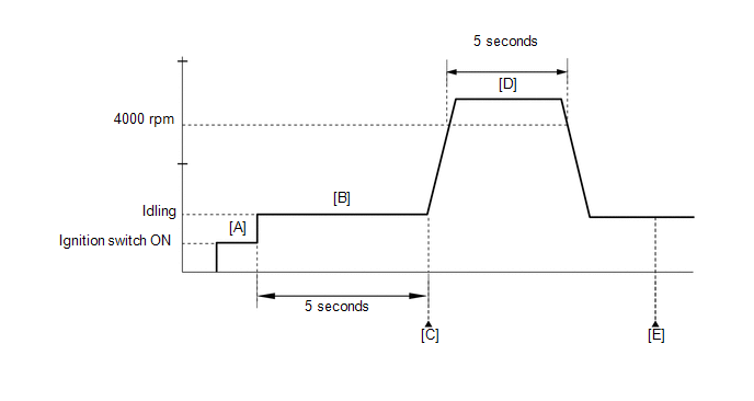
- Turn the ignition switch to ON and turn the Techstream on [A].
- Start the engine.
- Idle the engine for 5 seconds [B].
- Enter the following menus: Powertrain / Engine / Trouble Codes [C].
- Read the Pending DTCs.
HINT:
- If a pending DTC is output, the system is malfunctioning.
- If a pending DTC is not output, perform the following procedure.
- Run the engine at an engine speed of 4000 rpm or more for 5 seconds [D].
- Enter the following menus: Powertrain / Engine / Trouble Codes [E].
- Read the Pending DTCs.
HINT:
- If a pending DTC is output, the system is malfunctioning.
- If a pending DTC is not output, perform the following procedure.
- Enter the following menus: Powertrain / Engine / Utility / All Readiness.
- Input the DTC: P0102 or P0103.
- Check the DTC judgment result.
Techstream Display
Description
NORMAL
- DTC judgment completed
- System normal
ABNORMAL
- DTC judgment completed
- System abnormal
INCOMPLETE
- DTC judgment not completed
- Perform driving pattern after confirming DTC enabling conditions
N/A
- Unable to perform DTC judgment
- Number of DTCs which do not fulfill DTC preconditions has reached ECU memory limit
HINT:
- If the judgment result shows NORMAL, the system is normal.
- If the judgment result shows ABNORMAL, the system has a malfunction.
- If the judgment result shows INCOMPLETE or N/A, perform steps [B] and [E] again.
- If the no pending DTC is output, perform a universal trip and check
for permanent DTCs (See page ).
HINT:
- If a permanent DTC is output, the system is malfunctioning.
- If no permanent DTC is output, the system is normal.
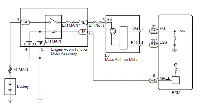
WIRING DIAGRAM
CAUTION / NOTICE / HINT
NOTICE:
Inspect the fuses for circuits related to this system before performing the following inspection procedure.
HINT:
Read freeze frame data using the Techstream. The ECM records vehicle and driving condition information as freeze frame data the moment a DTC is stored. When troubleshooting, freeze frame data can help determine if the vehicle was moving or stationary, if the engine was warmed up or not, if the air fuel ratio was lean or rich, and other data from the time the malfunction occurred.
PROCEDURE
|
1. |
READ DTC OUTPUT |
(a) Connect the Techstream to the DLC3.
(b) Turn the ignition switch to ON.
(c) Turn the Techstream on.
(d) Enter the following menus: Powertrain / Engine / Trouble Codes.
(e) Read the DTCs.
|
Result |
Proceed to |
|---|---|
|
DTC P0102 is output |
A |
|
DTC P0103 is output |
B |
| B | .gif) |
GO TO STEP 5 |
|
.gif)
|
2. |
INSPECT MASS AIR FLOW METER (POWER SOURCE VOLTAGE) |
|
(a) Disconnect the mass air flow meter connector. |
|
(b) Turn the ignition switch to ON.
(c) Measure the voltage according to the value(s) in the table below.
Standard Voltage:
|
Tester Connection |
Switch Condition |
Specified Condition |
|---|---|---|
|
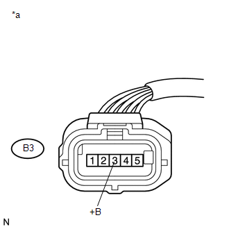
B3-3 (+B) - Body ground |
Ignition switch ON |
11 to 14 V |
|
*a |
Front view of wire harness connector (to Mass Air Flow Meter) |
| NG | |
REPAIR OR REPLACE HARNESS OR CONNECTOR (EFI MAIN RELAY - MASS AIR FLOW METER) |
|
|
3. |
CHECK HARNESS AND CONNECTOR (MASS AIR FLOW METER - ECM) |
(a) Disconnect the mass air flow meter connector.
(b) Disconnect the ECM connector.
(c) Measure the resistance according to the value(s) in the table below.
Standard Resistance (Check for Open):
|
Tester Connection |
Condition |
Specified Condition |
|---|---|---|
|
B3-5 (VG) - B58-94 (VG) |
Always |
Below 1 Ω |
|
B3-4 (E2G) - B58-117 (E2G) |
Always |
Below 1 Ω |
Standard Resistance (Check for Short):
|
Tester Connection |
Condition |
Specified Condition |
|---|---|---|
|
B3-5 (VG) or B58-94 (VG) - Body ground |
Always |
10 kΩ or higher |
| NG | |
REPAIR OR REPLACE HARNESS OR CONNECTOR |
|
|
4. |
INSPECT MASS AIR FLOW METER |
(a) Perform On-vehicle Inspection (See page
).
(b) Perform Inspection (See page ).
(c) Inspect the function of the mass air flow meter.
(1) Connect the Techstream to the DLC3.
(2) Turn the ignition switch to ON.
(3) Turn the Techstream on.
(4) Start the engine.
(5) Enter the following menus: Powertrain / Engine / Data List / MAF.
(6) Check that the reading of the MAF value changes when the engine is raced.
OK:
The reading changes.
HINT:
Perform "Inspection After Repair" after replacing the mass air flow meter (See
page ).
| OK | |
REPLACE ECM |
| NG | |
REPLACE MASS AIR FLOW METER |
|
5. |
CHECK HARNESS AND CONNECTOR (SENSOR GROUND) |
(a) Disconnect the mass air flow meter connector.
(b) Measure the resistance according to the value(s) in the table below.
Standard Resistance (Check for Open):
|
Tester Connection |
Condition |
Specified Condition |
|---|---|---|
|
B3-4 (E2G) - Body ground |
Always |
Below 1 Ω |
HINT:
Perform "Inspection After Repair" after replacing the mass air flow meter (See
page ).
| OK | |
REPLACE MASS AIR FLOW METER |
|
|
6. |
CHECK HARNESS AND CONNECTOR (MASS AIR FLOW METER - ECM) |
(a) Disconnect the mass air flow meter connector.
(b) Disconnect the ECM connector.
(c) Measure the resistance according to the value(s) in the table below.
Standard Resistance (Check for Open):
|
Tester Connection |
Condition |
Specified Condition |
|---|---|---|
|
B3-4 (E2G) - B58-117 (E2G) |
Always |
Below 1 Ω |
| OK | |
REPLACE ECM |
| NG | |
REPAIR OR REPLACE HARNESS OR CONNECTOR |
 Mass Air Flow Circuit Range / Performance Problem (P0101)
DESCRIPTION
Refer to DTC P0102 (See page ).
DTC No.
DTC Detection Condition
Trouble Area
P0101
All of the following conditions are met ( ...
 Intake Air Temperature Sensor Gradient Too High (P0111)
DESCRIPTION
The intake air temperature sensor, mounted on the mass air flow meter,
monitors the intake air temperature. The intake air temperature sensor has
a built-in thermistor wi ...
Other materials about Toyota Venza:
Registered Device cannot be Deleted
PROCEDURE
1.
DELETE OPERATION
(a) Check if a registered portable player can be deleted normally.
OK:
Registered portable player can be deleted normally.
OK
END
NG
PROCEED TO ...
Reassembly
REASSEMBLY
PROCEDURE
1. INSTALL NO. 1 SUNSHADE TRIM SUB-ASSEMBLY
(a) Slide and install the No. 1 sunshade trim sub-assembly.
2. INSTALL NO. 2 SUNSHADE TRIM SUB-ASSEMBLY
(a) Slide and ins ...
Audio Receiver Assembly Communication Stop Mode
DESCRIPTION
Detection Item
Symptom
Trouble Area
Audio Receiver Assembly Communication Stop Mode
"Display and Navigation (AVN1)" is not displayed on the "CAN
Bus Check ...

0.1848