Toyota Venza: Inspection
INSPECTION
PROCEDURE
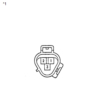
1. INSPECT COMPRESSOR AND MAGNETIC CLUTCH (A/C LOCK SENSOR)
|
(a) Measure the resistance according to the value(s) in the table below. Standard Resistance:
If the resistance is not as specified, replace the compressor and magnetic clutch. Text in Illustration
|
|
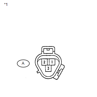
2. INSPECT COMPRESSOR AND MAGNETIC CLUTCH (A/C COMPRESSOR SOLENOID)
|
(a) Measure the resistance according to the value(s) in the table below. Standard Resistance:
If the resistance is not as specified, replace the compressor and magnetic clutch. Text in Illustration
|
|
.png)
3. INSPECT COMPRESSOR AND MAGNETIC CLUTCH
|
(a) Disconnect the connector from the compressor and magnetic clutch. |
|
|
(b) Disconnect the connector from the magnetic clutch. |
|
(c) Measure the resistance according to the value(s) in the table below.
Standard Resistance:
|
Tester Connection |
Condition |
Specified Condition |
|---|---|---|
|
A-3 - B-1 |
Always |
Below 1 Ω |
|
A-3 - Body ground |
Always |
10 kΩ or higher |
If the resistance is not as specified, replace the compressor and magnetic clutch.
Text in Illustration|
*1 |
Component without harness connected (A/C Compressor) |
|
*2 |
Front view of wire harness connector (to Magnetic Clutch) |
4. INSPECT MAGNETIC CLUTCH
|
(a) Measure the resistance according to the value(s) in the table below. Standard Resistance:
If the resistance is not as specified, replace the magnetic clutch. |
|
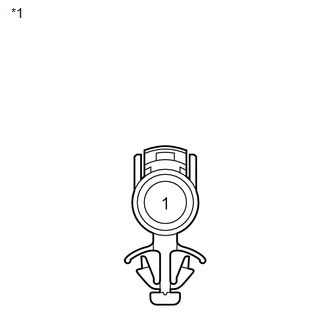
(b) When connector terminal 1 is connected to the positive (+) battery terminal, check that the following occurs: 1) the magnetic clutch's operating sound can be heard, and 2) the magnetic clutch's hub and rotor lock.
OK:
1)
The magnetic clutch's operating sound can be heard.
2)
The magnetic clutch's hub and rotor lock.
If the result is not as specified, replace the magnetic clutch.
Text in Illustration|
*1 |
Component without harness connected (Magnetic Clutch) |
 Disassembly
DISASSEMBLY
PROCEDURE
1. REMOVE MAGNETIC CLUTCH ASSEMBLY
(a) Place the compressor and magnetic clutch in a vise.
(b) Using SST, hold the m ...
 Installation
INSTALLATION
PROCEDURE
1. TEMPORARILY TIGHTEN COMPRESSOR AND MAGNETIC CLUTCH
(a) Temporarily install the compressor and magnetic clutch and bracket
with the 4 bolts.
...
Other materials about Toyota Venza:
Rear Spoiler
Components
COMPONENTS
ILLUSTRATION
Removal
REMOVAL
PROCEDURE
1. REMOVE UPPER BACK WINDOW PANEL TRIM
2. REMOVE REAR SPOILER ASSEMBLY
(a) Disconnect the connector.
(b) Remove the 2 hole ...
TS and CG Terminal Circuit
DESCRIPTION
In the Test Mode (signal check), a malfunction in the speed sensor that cannot
be detected when the vehicle is stopped can be detected while driving.
Transition to the sensor check mode can be performed by connecting terminals
TS and CG of th ...
Touch Panel Switch does not Function
PROCEDURE
1.
CHECK MULTI-DISPLAY
(a) Check if there is any foreign matter caught between the display and exterior
frame of the multi-display.
OK:
No foreign matter is caught between the display and exterior frame of the m ...

0.1723