Toyota Venza: If your vehicle has to be stopped in an emergency
Only in an emergency, such as if it becomes impossible to stop the vehicle in the normal way, stop the vehicle using the following procedure:
 Steadily step on the brake pedal
with both feet and firmly depress it.
Do not pump the brake pedal repeatedly as this will increase the effort required to slow the vehicle.
 Shift the shift lever to N.
If the shift lever is shifted to N
 After slowing down, stop the vehicle
in a safe place by the road.
 Stop the engine.
If the shift lever cannot be shifted to N
Keep depressing the brake pedal
with both feet to reduce vehicle speed as much as possible.
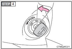
Vehicles without a smart key system: Stop the engine by turning the engine switch to the “ACC” position.
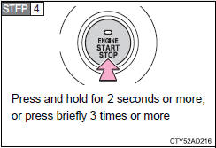
Vehicles with a smart key system:
To stop the engine, press and hold the “ENGINE START STOP” switch for 2 consecutive seconds or more, or press it briefly 3 times or more in succession.
 Stop the vehicle in a safe place
by the road.
CAUTION
- If the engine has to be turned off while driving
• Power assist for the brakes and steering wheel will be lost, making the brake pedal harder to depress and the steering wheel heavier to turn.
Decelerate as much as possible before turning off the engine.
• Vehicles without a smart key system: Never attempt to remove the key, as doing so will lock the steering wheel.
 If the vehicle becomes stuck
Carry out the following procedures if the tires spin or the vehicle becomes
stuck in mud, dirt, or snow.
Stop the engine. Set the parking
brake and shift the shift lever in “P”.
Stop the eng ...
 Vehicle specifications
Detailed vehicle information ...
Other materials about Toyota Venza:
Pressure Control Solenoid "D" Electrical (Shift Solenoid Valve SLT) (P2716)
DESCRIPTION
Refer to DTC P2714 (See page ).
DTC No.
DTC Detection Condition
Trouble Area
P2716
Open or short is detected in shift solenoid valve SLT circuit for 1 second
or more while driving ...
MIL Circuit
DESCRIPTION
The MIL (Malfunction Indicator Lamp) is used to indicate vehicle malfunctions
detected by the ECM. By turning the ignition switch to ON, power is supplied to
the MIL circuit, and the ECM provides the circuit ground which illuminates the MIL.
...
Removal
REMOVAL
CAUTION / NOTICE / HINT
PROCEDURE
1. PRECAUTION
NOTICE:
After turning the ignition switch off, waiting time may be required before disconnecting
the cable from the negative (-) battery terminal. Therefore, make sure to read the
disconnecting t ...

0.1266