Toyota Venza: Inspection
INSPECTION
PROCEDURE
1. INSPECT FRONT POWER WINDOW REGULATOR MOTOR ASSEMBLY LH
|
(a) Apply positive (+) battery voltage to connector terminal 2 (B). NOTICE: Do not apply positive (+) battery voltage to any terminals other than terminal 2 (B) to avoid damaging the pulse sensor inside the motor. |
|
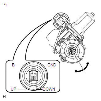
(b) Connect a ground lead to connector terminals 1 (GND) and 7 (DOWN) or 10 (UP).
(c) Check that the motor gear rotates smoothly as follows:
OK:
|
Measurement Condition |
Specified Condition |
|---|---|
|
Motor gear rotates clockwise (Up) |
|
Motor gear rotates counterclockwise (Down) |
|
*1 |
Component without harness connected (to Front Power Window Regulator Motor Assembly LH) |
- If the result is not as specified, replace the front power window regulator motor assembly LH.
CAUTION:
Reset the power window regulator motor (initialize the pulse sensor) after installing the power window regulator motor and regulator assembly onto the door.
2. INSPECT FRONT POWER WINDOW REGULATOR MOTOR ASSEMBLY RH
|
(a) Apply positive (+) battery voltage to connector terminal 2 (B). NOTICE: Do not apply positive (+) battery voltage to any terminals other than terminal 2 (B) to avoid damaging the pulse sensor inside the motor. |
|
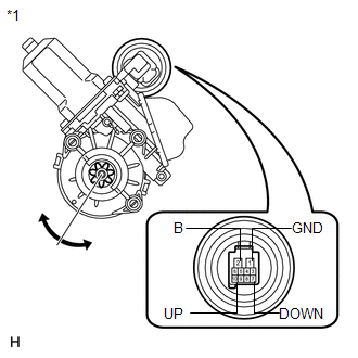
(b) Connect a ground lead to connector terminals 1 (GND) and 7 (DOWN) or 10 (UP).
(c) Check that the motor gear rotates smoothly as follows:
OK:
|
Measurement Condition |
Specified Condition |
|---|---|
|
Motor gear rotates counterclockwise (Up) |
|
Motor gear rotates clockwise (Down) |
|
*1 |
Component without harness connected (to Front Power Window Regulator Motor Assembly RH) |
- If the result is not as specified, replace the front power window regulator motor assembly RH.
CAUTION:
Reset the power window regulator motor (initialize the pulse sensor) after installing the power window regulator motor and regulator assembly onto the door.
 Removal
REMOVAL
CAUTION / NOTICE / HINT
HINT:
Use the same procedure for the RH side and LH side.
The procedure listed below is for the LH side.
PROCEDURE
1. DISCONNECT CABLE FROM NEGAT ...
 Installation
INSTALLATION
CAUTION / NOTICE / HINT
HINT:
Use the same procedure for the RH side and LH side.
The procedure listed below is for the LH side.
PROCEDURE
1. INSTALL FRONT POWER WI ...
Other materials about Toyota Venza:
Passenger Side Buckle Switch Circuit Malfunction (B1771)
DESCRIPTION
The passenger side buckle switch circuit consists of the occupant classification
ECU and front seat inner belt assembly RH.
DTC B1771 is recorded when a malfunction is detected in the passenger side buckle
switch circuit.
Troubleshoot DTC B1 ...
Removal
REMOVAL
PROCEDURE
1. ALIGN FRONT WHEELS FACING STRAIGHT AHEAD
2. DISCONNECT CABLE FROM NEGATIVE BATTERY TERMINAL
NOTICE:
When disconnecting the cable, some systems need to be initialized after the cable
is reconnected (See page ).
3. REMOVE FRONT WHEE ...
USB Audio System Recognition/Play Error
DESCRIPTION
When a USB device or "iPod" is connected to the USB jack of the No. 1 stereo
jack adapter assembly, it must have playable files. The device must also communicate
with and be recognized by the radio and display receiver assembly. This ...

0.1783