Toyota Venza: Inspection
INSPECTION
PROCEDURE
1. INSPECT OUTER REAR VIEW MIRROR ASSEMBLY RH
(a) Check the operation of the mirror surface.
|
(1) Disconnect the outer rear view mirror assembly RH connector. |
|
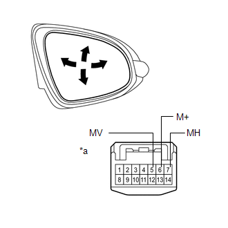
(2) Apply battery voltage and check the operation of the mirror.
OK:
|
Measurement Condition |
Specified Condition |
|---|---|
|
Battery positive (+) → Terminal 5 (MV) Battery negative (-) → Terminal 6 (M+) |
Turns upward |
|
Battery positive (+) → Terminal 6 (M+) Battery negative (-) → Terminal 5 (MV) |
Turns downward |
|
Battery positive (+) → Terminal 7 (MH) Battery negative (-) → Terminal 6 (M+) |
Turns left |
|
Battery positive (+) → Terminal 6 (M+) Battery negative (-) → Terminal 7 (MH) |
Turns right |
|
*a |
Component without harness connected (Outer Rear View Mirror Assembly RH) |
If the result is not as specified, replace the outer rear view mirror assembly RH.
(b) Check the operation of the retractable mirror. (w/ Retract Mirror)
NOTICE:
- Disconnect and reconnect the battery between each mirror position check.
- The mirror position cannot be changed manually when the battery is connected. To change the mirror position manually, the battery must be disconnected first.
|
(1) Disconnect the outer rear view mirror assembly RH connector. |
|
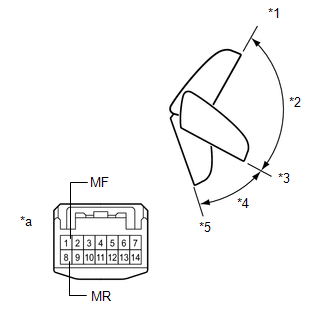
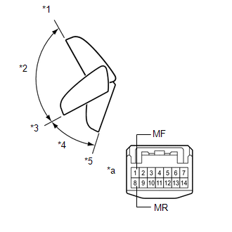
(2) For each position: Disconnect the battery, set the mirror position by hand, connect the battery, and check the retractable mirror movement.
OK:
|
Tester Connection |
Condition |
Specified Condition |
|---|---|---|
|
Battery positive (+) → Terminal 8 (MR) Battery negative (-) → Terminal 1 (MF) |
Forward position (A) |
Does not move |
|
Battery positive (+) → Terminal 1 (MF) Battery negative (-) → Terminal 8 (MR) |
Forward position (A) |
Moves from (A) to (E) |
|
Battery positive (+) → Terminal 8 (MR) Battery negative (-) → Terminal 1 (MF) |
Position between forward position (A) and driving position (C) |
Moves from (B) to (A) |
|
Battery positive (+) → Terminal 1 (MF) Battery negative (-) → Terminal 8 (MR) |
Position between forward position (A) and driving position (C) |
Moves from (B) to (E) |
|
Battery positive (+) → Terminal 8 (MR) Battery negative (-) → Terminal 1 (MF) |
Driving position (C) |
Does not move |
|
Battery positive (+) → Terminal 1 (MF) Battery negative (-) → Terminal 8 (MR) |
Driving position (C) |
Moves from (C) to (E) |
|
Battery positive (+) → Terminal 8 (MR) Battery negative (-) → Terminal 1 (MF) |
Position between driving position (C) and retracted position (E) |
Moves from (D) to (C) |
|
Battery positive (+) → Terminal 1 (MF) Battery negative (-) → Terminal 8 (MR) |
Position between driving position (C) and retracted position (E) |
Moves from (D) to (E) |
|
Battery positive (+) → Terminal 8 (MR) Battery negative (-) → Terminal 1 (MF) |
Retracted position (E) |
Moves from (E) to (C) |
|
Battery positive (+) → Terminal 1 (MF) Battery negative (-) → Terminal 8 (MR) |
Retracted position (E) |
Does not move |
|
*1 |
(A) Forward Position |
|
*2 |
(B) |
|
*3 |
(C) Driving position |
|
*4 |
(D) |
|
*5 |
(E) Retracted Position |
|
*a |
Component without harness connected (Outer Rear View Mirror Assembly RH) |
If the result is not as specified, replace the outer rear view mirror assembly RH.
(c) Check the operation of the mirror heater.
|
(1) Disconnect the outer rear view mirror assembly RH connector. |
|
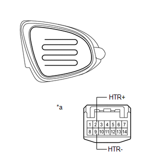
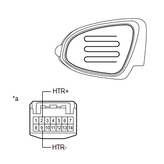
(2) Measure the resistance according to the value(s) in the table below.
Standard Resistance:
|
Tester Connection |
Condition |
Specified Condition |
|---|---|---|
|
2 (HTR+) - 9 (HTR-) |
25°C (75°F) |
7.6 to 11.4 Ω |
|
*a |
Component without harness connected (Outer Rear View Mirror Assembly RH) |
If the result is not as specified, replace the outer rear view mirror assembly RH.
(3) Connect the cable from the positive (+) terminal to terminal 2 and the negative battery (-) terminal to terminal 9, then check that the mirror becomes warm.
HINT:
It takes a short time for the mirror to become warm.
OK:
Mirror becomes warm.
If the result is not as specified, replace the outer rear view mirror assembly RH.
2. INSPECT OUTER REAR VIEW MIRROR ASSEMBLY LH
(a) Check the operation of the mirror surface.
|
(1) Disconnect the outer rear view mirror assembly LH connector. |
|
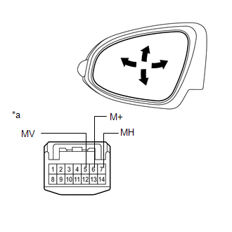
(2) Apply battery voltage and check the operation of the mirror.
OK:
|
Measurement Condition |
Specified Condition |
|---|---|
|
Battery positive (+) → Terminal 5 (MV) Battery negative (-) → Terminal 6 (M+) |
Turns upward |
|
Battery positive (+) → Terminal 6 (M+) Battery negative (-) → Terminal 5 (MV) |
Turns downward |
|
Battery positive (+) → Terminal 7 (MH) Battery negative (-) → Terminal 6 (M+) |
Turns left |
|
Battery positive (+) → Terminal 6 (M+) Battery negative (-) → Terminal 7 (MH) |
Turns right |
|
*a |
Component without harness connected (Outer Rear View Mirror Assembly LH) |
If the result is not as specified, replace the outer rear view mirror assembly LH.
(b) Check the operation of the retractable mirror. (w/ Retract Mirror)
NOTICE:
- Disconnect and reconnect the battery between each mirror position check.
- The mirror position cannot be changed manually when the battery is connected. To change the mirror position manually, the battery must be disconnected first.
|
(1) Disconnect the outer rear view mirror assembly LH connector. |
|
(2) For each position: Disconnect the battery, set the mirror position by hand, connect the battery, and check the retractable mirror movement.
OK:
|
Tester Connection |
Condition |
Specified Condition |
|---|---|---|
|
Battery positive (+) → Terminal 8 (MR) Battery negative (-) → Terminal 1 (MF) |
Forward position (A) |
Does not move |
|
Battery positive (+) → Terminal 1 (MF) Battery negative (-) → Terminal 8 (MR) |
Forward position (A) |
Moves from (A) to (E) |
|
Battery positive (+) → Terminal 8 (MR) Battery negative (-) → Terminal 1 (MF) |
Position between forward position (A) and driving position (C) |
Moves from (B) to (A) |
|
Battery positive (+) → Terminal 1 (MF) Battery negative (-) → Terminal 8 (MR) |
Position between forward position (A) and driving position (C) |
Moves from (B) to (E) |
|
Battery positive (+) → Terminal 8 (MR) Battery negative (-) → Terminal 1 (MF) |
Driving position (C) |
Does not move |
|
Battery positive (+) → Terminal 1 (MF) Battery negative (-) → Terminal 8 (MR) |
Driving position (C) |
Moves from (C) to (E) |
|
Battery positive (+) → Terminal 8 (MR) Battery negative (-) → Terminal 1 (MF) |
Position between driving position (C) and retracted position (E) |
Moves from (D) to (C) |
|
Battery positive (+) → Terminal 1 (MF) Battery negative (-) → Terminal 8 (MR) |
Position between driving position (C) and retracted position (E) |
Moves from (D) to (E) |
|
Battery positive (+) → Terminal 8 (MR) Battery negative (-) → Terminal 1 (MF) |
Retracted position (E) |
Moves from (E) to (C) |
|
Battery positive (+) → Terminal 1 (MF) Battery negative (-) → Terminal 8 (MR) |
Retracted position (E) |
Does not move |
|
*1 |
(A) Forward Position |
|
*2 |
(B) |
|
*3 |
(C) Driving position |
|
*4 |
(D) |
|
*5 |
(E) Retracted Position |
|
*a |
Component without harness connected (Outer Rear View Mirror Assembly LH) |
If the result is not as specified, replace the outer rear view mirror assembly LH.
(c) Check the operation of the mirror heater.
|
(1) Disconnect the outer rear view mirror assembly LH connector. |
|
(2) Measure the resistance according to the value(s) in the table below.
Standard Resistance:
|
Tester Connection |
Condition |
Specified Condition |
|---|---|---|
|
2 (HTR+) - 9 (HTR-) |
25°C (75°F) |
7.6 to 11.4 Ω |
|
*a |
Component without harness connected (Outer Rear View Mirror Assembly LH) |
If the result is not as specified, replace the outer rear view mirror assembly LH.
(3) Connect the cable from the positive (+) terminal to terminal 2 and the negative battery (-) terminal to terminal 8, then check that the mirror becomes warm.
HINT:
It takes a short time for the mirror to become warm.
OK:
Mirror becomes warm.
If the result is not as specified, replace the outer rear view mirror assembly LH.
 Disassembly
DISASSEMBLY
PROCEDURE
1. REMOVE OUTER MIRROR
2. REMOVE OUTER MIRROR LIGHT ASSEMBLY
3. REMOVE OUTER MIRROR COVER
4. REMOVE SIDE TURN SIGNAL LIGHT ASSEMBLY
...
 Reassembly
REASSEMBLY
PROCEDURE
1. INSTALL SIDE TURN SIGNAL LIGHT ASSEMBLY
2. INSTALL OUTER MIRROR COVER
3. INSTALL OUTER MIRROR LIGHT ASSEMBLY
4. INSTALL OUTER MIRROR
...
Other materials about Toyota Venza:
Hydraulic Test
HYDRAULIC TEST
1. PERFORM HYDRAULIC TEST
(a) Measure the line pressure.
CAUTION:
The line pressure test should always be carried out with at least 2 people. One
person should observe the condition of wheels and wheel chocks while the other is
perform ...
Reassembly
REASSEMBLY
PROCEDURE
1. BEARING POSITION
(a) Check each bearing position and installation direction.
Mark
Front Race Diameter
Inside / Outside mm (in.)
Thrust Bearing Diameter
Inside / Outside mm (in.)
...
Disassembly
DISASSEMBLY
PROCEDURE
1. REMOVE ULTRASONIC SENSOR CLIP (w/ Intuitive Parking Assist System)
2. REMOVE NO. 1 ULTRASONIC SENSOR (w/ Intuitive Parking Assist System)
3. REMOVE NO. 1 ULTRASONIC SENSOR RETAINER (w/ Intuitive Parking Assist System)
4. ...

0.1166