Toyota Venza: Inspection
INSPECTION
PROCEDURE
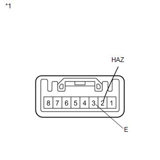
1. INSPECT DRIVE MONITOR SWITCH
|
(a) Measure the resistance according to the value(s) in the table below. Standard Resistance:
If the result is not as specified, replace the driver monitor switch. |
|
 Components
COMPONENTS
ILLUSTRATION
ILLUSTRATION
ILLUSTRATION
...
 Removal
REMOVAL
PROCEDURE
1. REMOVE UPPER CONSOLE PANEL SUB-ASSEMBLY (w/o Seat Heater System)
2. REMOVE UPPER CONSOLE PANEL SUB-ASSEMBLY (w/ Seat Heater System)
3. REMOVE NO. 2 CONSOLE BOX CARPET
...
Other materials about Toyota Venza:
Installation
INSTALLATION
PROCEDURE
1. INSTALL FRONT DRIVE SHAFT ASSEMBLY LH
(a) Align the splines of the shaft and install the drive shaft assembly
LH using a brass bar and a hammer.
NOTICE:
Set the shaft snap ring with the opening fac ...
Emission inspection and maintenance (I/M) programs
Some states have vehicle emission inspection programs which include OBD (On
Board Diagnostics) checks. The OBD system monitors the operation of the emission
control system.
- If the malfunction indicator lamp comes on
The OBD system determines that ...
How To Proceed With Troubleshooting
CAUTION / NOTICE / HINT
HINT:
Use the following procedure to troubleshoot the power steering system.
*: Use the Techstream.
PROCEDURE
1.
VEHICLE BROUGHT TO WORKSHOP
NEXT
...

0.1607