Toyota Venza: Removal
REMOVAL
PROCEDURE
1. REMOVE UPPER CONSOLE PANEL SUB-ASSEMBLY (w/o Seat Heater System)
.gif)
2. REMOVE UPPER CONSOLE PANEL SUB-ASSEMBLY (w/ Seat Heater System)
3. REMOVE NO. 2 CONSOLE BOX CARPET
4. REMOVE CONSOLE BOX ASSEMBLY
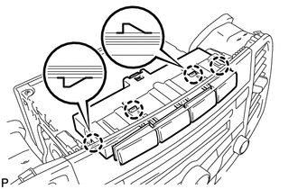
5. REMOVE AIR CONDITIONING CONTROL ASSEMBLY
6. REMOVE FRONT DOOR SCUFF PLATE LH
7. REMOVE COWL SIDE TRIM SUB-ASSEMBLY LH
8. REMOVE LOWER NO. 1 INSTRUMENT PANEL FINISH PANEL
9. REMOVE FRONT DOOR SCUFF PLATE RH
HINT:
Use the same procedure for the RH side and LH side.
10. REMOVE COWL SIDE TRIM SUB-ASSEMBLY RH
HINT:
Use the same procedure for the RH side and LH side.
11. REMOVE NO. 2 INSTRUMENT PANEL UNDER COVER SUB-ASSEMBLY
12. REMOVE LOWER INSTRUMENT PANEL SUB-ASSEMBLY
13. REMOVE SHIFT LEVER KNOB SUB-ASSEMBLY
14. REMOVE POSITION INDICATOR HOUSING ASSEMBLY
15. REMOVE CONSOLE BOX SUB-ASSEMBLY
16. REMOVE NO. 2 INSTRUMENT PANEL SPEAKER PANEL SUB-ASSEMBLY
17. REMOVE RADIO AND DISPLAY RECEIVER ASSEMBLY WITH BRACKET (for Radio and Display Type)
18. REMOVE NAVIGATION RECEIVER ASSEMBLY WITH BRACKET (for Navigation Receiver Type)
19. REMOVE DRIVE MONITOR SWITCH
|
(a) Using a screwdriver, disengage the 4 claws and remove the driver monitor switch. |
|
 Inspection
INSPECTION
PROCEDURE
1. INSPECT DRIVE MONITOR SWITCH
(a) Measure the resistance according to the value(s) in the table below.
Standard Resistance:
Tester Connecti ...
 Installation
INSTALLATION
PROCEDURE
1. INSTALL DRIVE MONITOR SWITCH
(a) Engage the 4 claws to install the driver monitor switch.
2. INSTALL RADIO AND D ...
Other materials about Toyota Venza:
No Communication in Immobiliser System (B2796,B2798)
DESCRIPTION
These DTCs are stored if a key that does not have a transponder chip is inserted
into the ignition key cylinder or if communication between the key and the transponder
key ECU assembly is impossible.
DTC No.
DTC Detectio ...
CD Sound Skips
PROCEDURE
1.
CHECK CD
(a) Check that the CD is not deformed or cracked.
OK:
No deformation or cracks on the CD
NG
END (CD IS FAULTY)
...
Dtc Check / Clear
DTC CHECK / CLEAR
1. CHECK DTC (When Using Techstream)
(a) Check the DTCs.
(1) Connect the Techstream to the DLC3.
(2) Turn the ignition switch to ON.
(3) Turn the Techstream on.
(4) Read the DTCs following the prompts on the Techstream screen. Enter the ...

0.1337