Toyota Venza: System Description
SYSTEM DESCRIPTION
1. OUTLINE OF THE COMBINATION METER ASSEMBLY
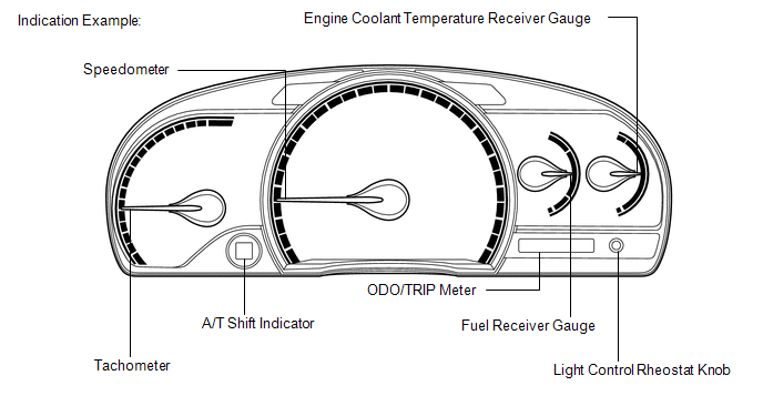
(a) Meter or Gauge
|
Item |
Detail |
|---|---|
|
Speedometer |
Indicates the vehicle speed based on a signal received from the skid control ECU. (CAN (CAN No. 1 Bus)) |
|
Tachometer |
Indicates the engine speed based on a signal received from the ECM. (CAN (CAN No. 1 Bus)) |
|
Fuel Receiver Gauge |
Indicates the fuel level based on a signal received from the fuel sender gauge assembly. (Direct Line) |
|
Engine Coolant Temperature Receiver Gauge |
Indicates the engine coolant temperature based on a signal received from the ECM. (CAN (CAN No. 1 Bus)) |
(b) Warning, Indicator or Reminder
|
Item |
Detail |
|---|---|
|
High beam |
Receives a beam indicator light signal from the main body ECU (driver side junction block assembly). (CAN (CAN No. 1 Bus)) |
|
Turn |
Receives a turn signal from the turn signal flasher. (Direct Line) |
|
Fuel level |
Receives a fuel signal from the fuel sender gauge. (Direct Line) |
|
Brake |
Receives a brake signal from the brake fluid level warning switch (Direct Line) and the skid control ECU. (CAN (CAN No. 1 Bus)) |
|
SRS |
Receives an SRS signal from the center airbag sensor assembly. (CAN (CAN No. 1 Bus)) |
|
Open door |
Receives a door condition signal from the main body ECU (driver side junction block assembly). (CAN (CAN No. 1 Bus)) |
|
Oil pressure |
Receives an oil pressure warning light signal from the oil pressure switch. (Direct Line) |
|
Charge |
Receives a charge indicator light signal from the generator. (Direct Line) |
|
MIL (Check engine warning light) |
Receives a MIL (check engine warning light) signal from the ECM. (Direct Line) |
|
Driver side seat belt |
Receives a driver side seat belt signal from the main body ECU (driver side junction block assembly). (CAN (CAN No. 1 Bus)) |
|
ABS |
Receives an ABS signal from the skid control ECU. (CAN (CAN No. 1 Bus)) |
|
EPS |
Receives an EPS signal from the power steering ECU. (CAN (CAN No. 1 Bus)) |
|
Front fog |
Receives a front fog indicator light signal from the main body ECU (driver side junction block assembly). (CAN (CAN No. 1 Bus)) |
|
Headlight leveling*1 |
Receives a headlight leveling signal from the headlight leveling ECU assembly. (Direct Line) |
|
Automatic high beam*2 |
Receives an automatic high beam signal from the main body ECU (driver side junction block assembly). (CAN (CAN No. 1 Bus)) |
|
Tail |
Receives a tail signal from the main body ECU (driver side junction block assembly). (CAN (CAN No. 1 Bus)) |
|
Cruise SET |
Receives a cruise SET signal from the ECM. (CAN (CAN No. 1 Bus)) |
|
AWD*5 |
Receives an AWD signal from the AWD control ECU. (CAN (CAN No. 1 Bus)) |
|
VSC OFF |
Receives a VSC OFF signal from the skid control ECU. (CAN (CAN No. 1 Bus)) |
|
TRAC OFF |
Receives a TRAC OFF signal from the skid control ECU. (CAN (CAN No. 1 Bus)) |
|
Tire pressure |
Receives a tire pressure signal from the tire pressure warning ECU. (Direct Line) |
|
Washer level |
Receives a washer level signal from the washer level warning switch. (Direct Line) |
|
Key*3 |
Receives a key signal from the smart key ECU. (Direct Line) |
|
Security |
Receives a security indicator light signal from the certification ECU (smart key ECU assembly)*3 or transponder key ECU assembly*4. (Direct Line) |
|
Front passenger side airbag ON/OFF |
Receives a front passenger side airbag ON/OFF signal from the center airbag sensor assembly. (Direct Line) |
|
Master warning*6 |
Comes on when the reminder message or warning message appears on the multi-information display. |
|
Slip |
Receives a slip signal from the skid control ECU. (CAN (CAN No. 1 Bus)) |
|
Cruise |
Receives a cruise signal from the ECM. (CAN (CAN No. 1 Bus)) |
|
Front passenger side seat belt |
Receives a front passenger side seat belt buckle switch signal from the center airbag sensor assembly (CAN (CAN No. 1 Bus)) and transmits a front passenger side seat belt warning light signal to the accessory meter assembly. (Direct Line) |
|
A/T shift |
Receives an A/T shift condition signal from the park/neutral position switch (Direct Line) and the ECM. (CAN (CAN No. 1 Bus)) |
- *1: w/ Automatic Type Headlight Beam Level Control
- *2: w/ Automatic High Beam System
- *3: w/ Smart Key System
- *4: w/o Smart Key System
- *5: for AWD
- *6: w/ Multi-information Display
2. ACCESSORY METER ASSEMBLY
|
Item |
Detail |
|
|---|---|---|
|
Cruise information display |
Total driving distance*1 |
Six types of information (total driving distance*1, average fuel consumption, average vehicle speed, driving time*2, current fuel consumption, and driving range) can be displayed. |
|
Average fuel consumption |
||
|
Average vehicle speed |
||
|
Driving time*2 |
||
|
Current fuel consumption |
||
|
Driving range |
||
|
Multi-information display*2 |
Each system warning |
Interrupts the multi-information display immediately when a warning occurs. |
|
DTC (Diagnostic Trouble Code) display |
Displays 2 digit DTCs pertaining to the VSC function. |
|
|
Custom setting display |
Displays the customized setting of each item. |
|
|
Outside temperature |
Displays the outside temperature. |
|
|
Illumination control |
Displays the current illumination level and adjust the combination meter assembly brightness. |
|
|
ODO/TRIP meter |
Indicates the driving distance. |
|
- *1: w/o Multi-information Display
- *2: w/ Multi-information Display
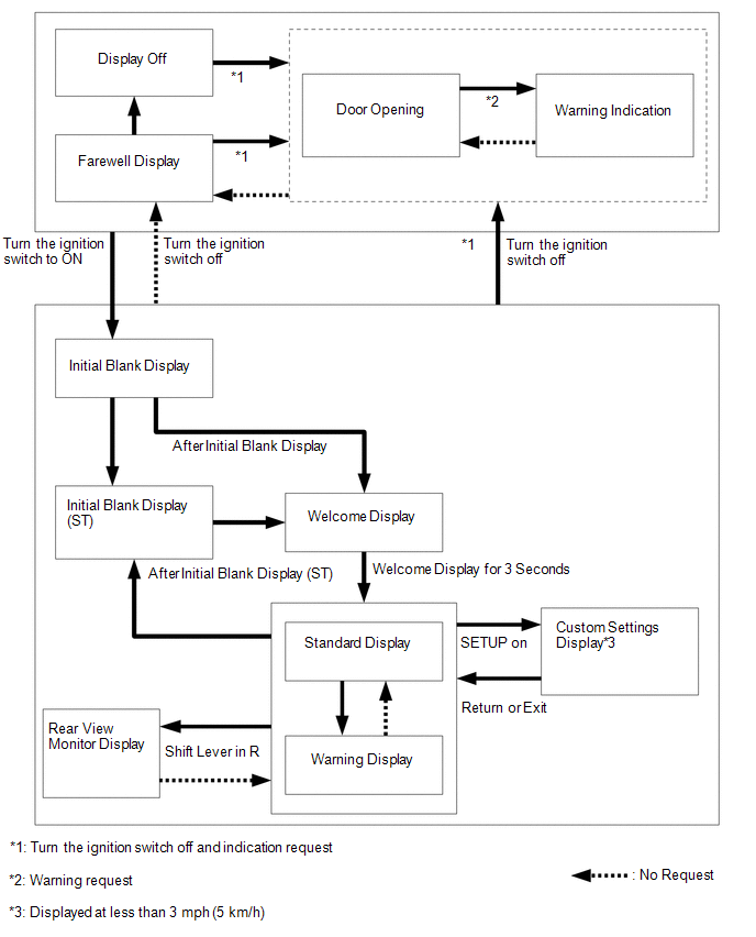
3. MULTI-INFORMATION DISPLAY FLOW CHART
(a) Multi-information Display Flow Chart
4. DIAGNOSIS SYSTEM
HINT:
- The multi-information display shows "DIAG" when turn the ignition switch
to ON (See page
.gif) ).
). - Diagnosis information can be displayed on the multi-information display after connecting a jumper wire between terminals TC and CG of the DLC3 connector.
5. LED INITIAL CHECK
(a) Check the illumination function of the warning, indicator, or reminder light listed below when turn the ignition switch to ON.
OK:
|
Warning or Indicator Light |
Specified Condition |
|---|---|
|
Brake, ABS, Slip, VSC OFF, TRAC OFF, Tire pressure, Washer level, Master warning*2 |
Warning or indicator light comes on for about 3 seconds after the ignition switch is turned to ON. |
|
SRS, Front passenger side seat belt |
Warning light comes on for about 6 seconds after the ignition switch is turned to ON. |
|
Charge, Oil pressure, MIL (Check engine), EPS, Front passenger side airbag ON/OFF |
Warning or indicator light comes on when the ignition switch is turned to ON before engine starts. |
|
AWD*1 |
Warning light comes on for about 4 seconds after the ignition switch is turned to ON. |
- *1: for AWD
- *2: w/ Multi-information Display
 How To Proceed With Troubleshooting
CAUTION / NOTICE / HINT
HINT:
Use the following procedure to troubleshoot.
*: Use the Techstream.
PROCEDURE
1.
VEHICLE BROUGHT TO WORKSHOP
...
 Customize Parameters
CUSTOMIZE PARAMETERS
1. CUSTOMIZE METER / GAUGE SYSTEM
(a) Customizing with the Techstream
(1) Connect the Techstream to the DLC3.
(2) Turn the ignition switch to ON.
(3) Turn the Techstream on.
...
Other materials about Toyota Venza:
How To Proceed With Troubleshooting
CAUTION / NOTICE / HINT
HINT:
*: Use the Techstream.
PROCEDURE
1.
VEHICLE BROUGHT TO WORKSHOP
NEXT
2.
CUSTOMER PROBLEM ANALYSIS
...
Disassembly
DISASSEMBLY
PROCEDURE
1. REMOVE SEAT ADJUSTER COVER CAP
(a) Remove the seat adjuster cover cap.
HINT:
Use the same procedure for the RH side and LH side.
2. REMOVE RECLINING POWER SEAT SWITCH ...
Dtc Check / Clear
DTC CHECK / CLEAR
1. CHECK DTC (When Using Techstream)
(a) Check the DTCs.
(1) Connect the Techstream to the DLC3.
(2) Turn the ignition switch to ON.
(3) Turn the Techstream on.
(4) Read the DTCs following the prompts on the Techstream screen. Enter the ...

0.1143