Toyota Venza: Components
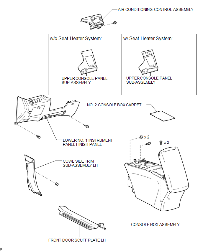
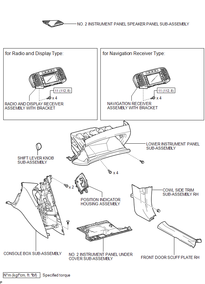
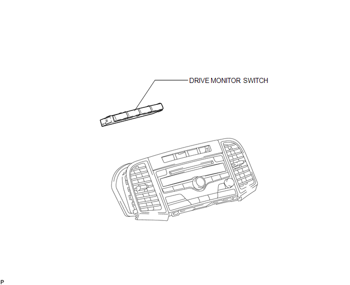
COMPONENTS
ILLUSTRATION
ILLUSTRATION
ILLUSTRATION

 Inspection
INSPECTION
PROCEDURE
1. INSPECT DRIVE MONITOR SWITCH
(a) Measure the resistance according to the value(s) in the table below.
Standard Resistance:
Tester Connecti ...
Other materials about Toyota Venza:
Removal
REMOVAL
PROCEDURE
1. REMOVE ROOF DRIP CENTER SIDE FINISH MOULDING (w/o Sliding Roof)
(a) Put protective tape around the roof drip center side finish moulding.
Text in Illustration
*1
Protective Tape
...
Reassembly
REASSEMBLY
PROCEDURE
1. INSTALL REAR SEAT LEG ASSEMBLY RH
(a) Using a T55 "TORX" socket wrench, install the rear seat leg assembly
RH with the 5 "TORX" bolts.
Torque:
A :
42 N·m {428 kgf·cm, 31 ft·lbf}
B : ...
How To Proceed With Troubleshooting
CAUTION / NOTICE / HINT
HINT:
*: Use the Techstream
PROCEDURE
1.
VEHICLE BROUGHT TO WORKSHOP
NEXT
2.
CUSTOMER PROBLEM ANALYSIS
...

0.1281