Toyota Venza: Disassembly
DISASSEMBLY
PROCEDURE
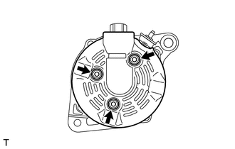
1. REMOVE GENERATOR REAR END COVER
|
(a) Remove the 3 nuts and generator rear end cover. |
|
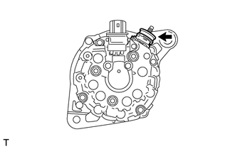
2. REMOVE TERMINAL INSULATOR
|
(a) Remove the terminal insulator from the generator coil. |
|
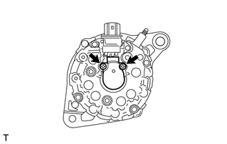
3. REMOVE GENERATOR BRUSH HOLDER ASSEMBLY
|
(a) Remove the 2 screws and brush holder from the generator coil. |
|
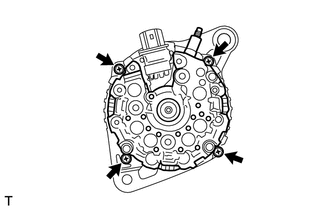
4. REMOVE GENERATOR COIL ASSEMBLY
|
(a) Remove the 4 bolts. |
|
|
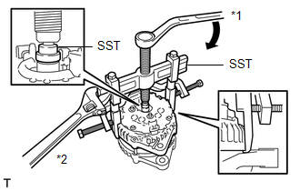
(b) Using SST, remove the generator coil assembly. Text in Illustration
SST: 09950-40011 09951-04020 09952-04010 09953-04020 09954-04010 09955-04071 09957-04010 09958-04011 |
|
|
(c) Remove the generator washer. |
|
.png)
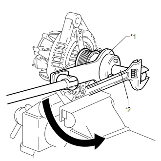
5. REMOVE GENERATOR CLUTCH PULLEY
|
(a) Using a screwdriver, remove the generator pulley cap. NOTICE: Do not reuse the generator pulley cap. |
|

(b) Mount the generator drive end frame in a vise tightly.
|
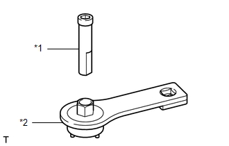
(c) Confirm SST (A) and (B) shown in the illustration. Text in Illustration
SST: 09820-63021 |
|
|
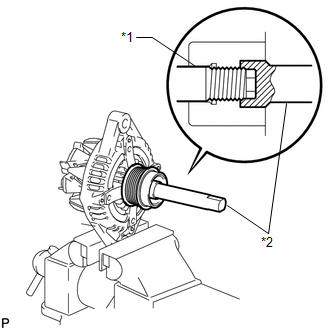
(d) Place the rotor shaft end into SST (A). Text in Illustration
|
|
|
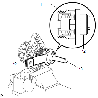
(e) Fit SST (B) to the clutch pulley. Text in Illustration
|
|
|
(f) Loosen the pulley by turning SST (B) in the direction shown in the illustration. Text in Illustration
NOTICE:
|
|
(g) Remove SST from the generator assembly.
(h) Remove the clutch pulley from the rotor shaft.
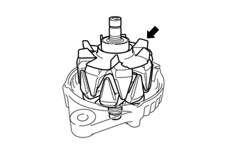
6. REMOVE GENERATOR ROTOR ASSEMBLY
|
(a) Remove the generator rotor assembly. |
|
 Removal
REMOVAL
PROCEDURE
1. DISCONNECT CABLE FROM NEGATIVE BATTERY TERMINAL
NOTICE:
When disconnecting the cable, some systems need to be initialized after the cable
is reconnected (See page ).
2. RE ...
 Inspection
INSPECTION
PROCEDURE
1. INSPECT GENERATOR CLUTCH PULLEY
(a) Hold the generator rotor using SST, and turn the clutch pulley clockwise
to check that the outer ring locks.
SST: 09820 ...
Other materials about Toyota Venza:
PIG Power Supply Voltage Malfunction (C1552)
DESCRIPTION
When a problem occurs in the power steering system, the power source relay circuit
is shut off to stop the power assist.
DTC No.
DTC Detection Condition
Trouble Area
C1552
PIG power s ...
Interior Light Power Source Circuit
DESCRIPTION
The main body ECU (driver side junction block assembly) controls operation of
the DOME CUT relay in order to supply power to the interior lights.
WIRING DIAGRAM
CAUTION / NOTICE / HINT
NOTICE:
Inspect the fuses for circuits related to this ...
Removal
REMOVAL
CAUTION / NOTICE / HINT
HINT:
Use the same procedure for the RH side and LH side.
The procedure listed below is for the LH side.
PROCEDURE
1. PRECAUTION
CAUTION:
Be sure to read Precaution thoroughly before servicing (See page
...

0.1607