Toyota Venza: Reassembly
REASSEMBLY
CAUTION / NOTICE / HINT
HINT:
Use high-temperature grease to lubricate the bearings, gears and return spring when assembling the starter.
PROCEDURE
1. INSTALL PLANETARY GEAR
|
(a) Apply grease to the planetary gears and pin parts of the planetary shaft. |
|
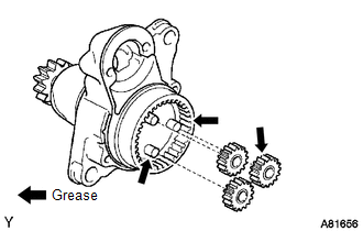
(b) Install the 3 planetary gears.
2. INSTALL STARTER ARMATURE ASSEMBLY
(a) Apply grease to the plate washer and the armature shaft.
NOTICE:
- Be sure to install the snap ring in the armature shaft groove securely.
- Be sure to properly install the snap ring because it expands easily.
(b) Install the starter armature to the starter commutator end frame.
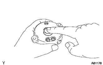
|
(c) Using snap ring pliers, install the plate washer and a new snap ring. Text in Illustration
|
|
.png)
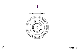
|
(d) Using a vernier caliper, measure the length of the snap ring. Text in Illustration
Maximum length: 5.0 mm (0.196 in.) If the length is greater than the maximum, replace it with a new snap ring. |
|
3. INSTALL STARTER COMMUTATOR END FRAME COVER
|
(a) Install the end frame cover to the commutator end frame. |
|
4. INSTALL STARTER ARMATURE PLATE
|
(a) Insert the starter armature plate to the starter yoke. Text in Illustration
|
|
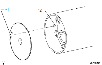
(b) Align the keyway of the starter armature plate with the key inside the starter yoke, and install the starter armature plate.
5. INSTALL STARTER COMMUTATOR END FRAME ASSEMBLY
|
(a) Align the rubber of the end frame with the cutout of the starter yoke. Text in Illustration
|
|
(b) Install the end frame to the starter yoke.
NOTICE:
The magnet of the starter yoke may attract the starter armature when the starter commutator end frame is installed, causing the magnet to break.
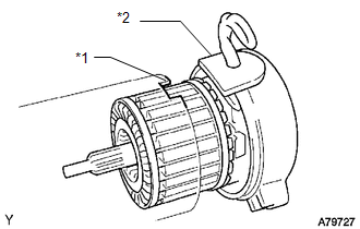
6. INSTALL STARTER YOKE ASSEMBLY
|
(a) Align the protrusion of the starter yoke with the cutout of the starter drive housing. Text in Illustration
|
|
|
(b) Install the starter yoke with the 2 through-bolts. Torque: 6.0 N·m {61 kgf·cm, 53 in·lbf} |
|
.png)
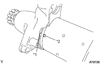
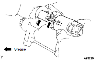
7. INSTALL MAGNETIC SWITCH ASSEMBLY
|
(a) Apply grease to the plunger and the hook. |
|
(b) Hang the plunger hook of the magnetic switch to the drive lever.
(c) Install the plunger and return spring.
|
(d) Install the magnetic switch with the 2 screws. Torque: 7.5 N·m {76 kgf·cm, 66 in·lbf} |
|
.png)
|
(e) Connect the lead wire to the magnetic switch with the nut. Torque: 10 N·m {102 kgf·cm, 7 ft·lbf} |
|
.png)
 Inspection
INSPECTION
PROCEDURE
1. INSPECT STARTER ASSEMBLY
NOTICE:
These tests must be performed within 3 to 5 seconds to avoid burning out the
coil.
(a) Perform a pull-in test.
(1) Remove the nut and d ...
 Installation
INSTALLATION
PROCEDURE
1. INSTALL STARTER ASSEMBLY
(a) Install the starter with the 2 bolts.
Torque:
37 N·m {377 kgf·cm, 27 ft·lbf}
...
Other materials about Toyota Venza:
Portable Player cannot be Operated Using In-vehicle Device or Track Information
is not Displayed on In-vehicle Device
PROCEDURE
1.
CHECK USING ANOTHER "Bluetooth" AUDIO COMPATIBLE VEHICLE OF SAME MODEL
(a) Check if track information is displayed normally on another "Bluetooth" audio
compatible vehicle of the same model.
...
Installation
INSTALLATION
PROCEDURE
1. INSTALL WINDSHIELD WIPER SWITCH ASSEMBLY
(a) Engage the claw to install the windshield wiper switch assembly as
shown in the illustration.
(b) Connect the 2 connectors. ...
Installation
INSTALLATION
PROCEDURE
1. INSTALL REAR DRIVE SHAFT ASSEMBLY
(a) Align the shaft splines and install the rear drive shaft assembly
using a screwdriver and hammer.
NOTICE:
Set the snap ring with the opening facing downward.
...

0.1394