Toyota Venza: Camshaft Position Sensor
Components
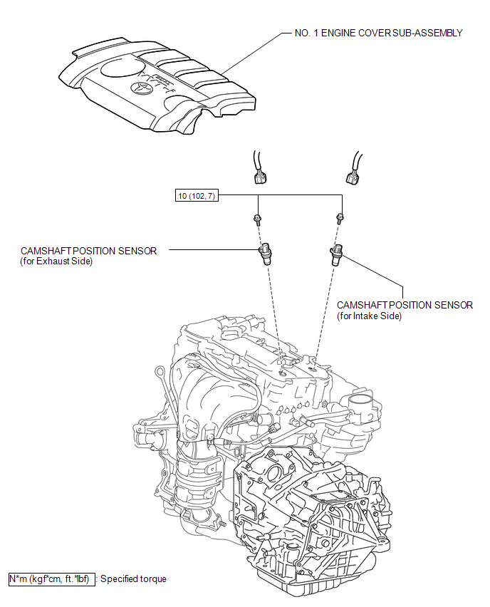
COMPONENTS
ILLUSTRATION
Installation
INSTALLATION
PROCEDURE
1. INSTALL CAMSHAFT POSITION SENSOR (for Exhaust Side)
(a) Apply a light coat of engine oil to the O-ring of the camshaft position sensor.
NOTICE:
If reusing the camshaft position sensor, be sure to inspect the O-ring.
(b) Install the camshaft position sensor to the cylinder head cover sub-assembly with the bolt.
Torque:
10 N·m {102 kgf·cm, 7 ft·lbf}
NOTICE:
- If the camshaft position sensor has been struck or dropped, replace it.
- Make sure that the O-ring is not cracked or moved out of place when installing the camshaft position sensor.
(c) Connect the camshaft position sensor connector.
2. INSTALL CAMSHAFT POSITION SENSOR (for Intake Side)
(a) Apply a light coat of engine oil to the O-ring of the camshaft position sensor.
NOTICE:
If reusing the camshaft position sensor, be sure to inspect the O-ring.
(b) Install the camshaft position sensor with the bolt.
Torque:
10 N·m {102 kgf·cm, 7 ft·lbf}
NOTICE:
- If the camshaft position sensor has been struck or dropped, replace it.
- Make sure that the O-ring is not cracked or moved out of place when installing the camshaft position sensor.
(c) Connect the camshaft position sensor connector.
3. INSPECT FOR OIL LEAK
4. INSTALL NO. 1 ENGINE COVER SUB-ASSEMBLY
.gif)
Removal
REMOVAL
PROCEDURE
1. REMOVE NO. 1 ENGINE COVER SUB-ASSEMBLY
.gif)
2. REMOVE CAMSHAFT POSITION SENSOR (for Exhaust Side)
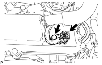
(a) Disconnect the sensor connector.
(b) Remove the bolt and sensor.
3. REMOVE CAMSHAFT POSITION SENSOR (for Intake Side)
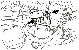
(a) Disconnect the sensor connector.
(b) Remove the bolt and sensor.
 Installation
INSTALLATION
PROCEDURE
1. INSTALL CAMSHAFT TIMING OIL CONTROL VALVE ASSEMBLY (for Exhaust Side)
(a) Apply a light coat of engine oil to a new O-ring, and install it
to the oil contro ...
 Crankshaft Position Sensor
Components
COMPONENTS
ILLUSTRATION
Removal
REMOVAL
PROCEDURE
1. REMOVE FRONT FENDER APRON SEAL RH
2. REMOVE CRANKSHAFT POSITION SENSOR
(a) Disconnect the sensor connector.
(b) Remo ...
Other materials about Toyota Venza:
Operation Check
OPERATION CHECK
1. CHECK REMOTE CONTROL MIRROR FUNCTION
(a) Turn the ignition switch ON.
(b) With the mirror select switch set to L, check that the outer rear view mirror
LH surface moves up, down, left and right normally.
(c) With the mirror select swit ...
HD Radio Tuner Malfunction (B1551,B15A0,B15AD,B15B0,B15B3,B15B4,B15B7)
DESCRIPTION
These DTCs are stored when a malfunction occurs in the navigation receiver assembly.
DTC No.
DTC Detection Condition
Trouble Area
B1551
When any of the following conditions is met:
...
Operation Check
OPERATION CHECK
1. CHECK NAVIGATION SYSTEM NORMAL CONDITION
(a) If the symptom is applicable to any of the following, it is intended behavior,
and not a malfunction.
Symptom
Answer
A longer route than expected is cho ...

0.1727