Toyota Venza: Inspection
INSPECTION
PROCEDURE
1. INSPECT ENGINE SWITCH
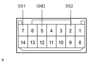
(a) Measure the resistance according to the value(s) in the table below.
Standard Resistance:
|
Tester Connection |
Switch Condition |
Specified Condition |
|---|---|---|
|
7 (SS1) - 5 (GND) |
Not pushed |
10 kΩ or higher |
|
2 (SS2) - 5 (GND) |
Not pushed |
10 kΩ or higher |
|
7 (SS1) - 5 (GND) |
Pushed |
15 Ω |
|
2 (SS2) - 5 (GND) |
Pushed |
15 Ω |
If the result is not as specified, replace the engine switch.
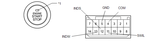
(b) Apply battery voltage between the terminals of the switch, and check the illumination condition of the engine switch.
HINT:
- If a positive (+) battery lead and a negative (-) battery lead are incorrectly connected, the engine switch indicator light will not illuminate.
- If the voltage is too low, the indicator light will not illuminate.
OK:
|
Measurement Condition |
Specified Condition |
|---|---|
|
Battery positive (+) → Terminal 11 (SWIL) Battery negative (-) → Terminal 4 (COM) or 5 (GND) |
Illuminates |
|
Battery positive (+) → Terminal 12 (INDS) Battery negative (-) → Terminal 4 (COM) or 5 (GND) |
Illuminates |
|
Battery positive (+) → Terminal 13 (INDW) Battery negative (-) → Terminal 4 (COM) or 5 (GND) |
Illuminates |
 Text in Illustration
|
*1 |
Indicator Light |
If the result is not as specified, replace the engine switch.
 Components
COMPONENTS
ILLUSTRATION
ILLUSTRATION
...
 Removal
REMOVAL
PROCEDURE
1. DISCONNECT CABLE FROM NEGATIVE BATTERY TERMINAL
NOTICE:
When disconnecting the cable, some systems need to be initialized after the cable
is reconnected (See page ).
2. RE ...
Other materials about Toyota Venza:
Front Passenger Side Power Mirror cannot be Adjusted with Power Mirror Switch
SYSTEM DESCRIPTION
When the mirror adjust switch is operated, the main body ECU (driver side junction
block assembly) detects the switch operation and sends the mirror adjust switch
signal to the outer mirror control ECU assembly (front passenger door) vi ...
How To Proceed With Troubleshooting
CAUTION / NOTICE / HINT
HINT:
Use the following procedure listed to troubleshoot the Active Torque
Control 4WD system.
*: Use the Techstream.
PROCEDURE
1.
VEHICLE BROUGHT TO WORKSHOP
...
Luggage compartment light
1. Door position
2. Off
- Adjusting the rear personal/interior lights angle
Push the edge of the light lens.
- To prevent the battery from being discharged
►Vehicles with smart key system
If the personal/interior lights and “ENGIN ...

0.1235