Toyota Venza: Removal
REMOVAL
PROCEDURE
1. DISCONNECT CABLE FROM NEGATIVE BATTERY TERMINAL
NOTICE:
When disconnecting the cable, some systems need to be initialized after the cable
is reconnected (See page .gif) ).
).
2. REMOVE UPPER CONSOLE PANEL SUB-ASSEMBLY (w/o Seat Heater System)
3. REMOVE UPPER CONSOLE PANEL SUB-ASSEMBLY (w/ Seat Heater System)
4. REMOVE NO. 2 CONSOLE BOX CARPET
5. REMOVE CONSOLE BOX ASSEMBLY
6. REMOVE AIR CONDITIONING CONTROL ASSEMBLY
7. REMOVE FRONT DOOR SCUFF PLATE LH
8. REMOVE COWL SIDE TRIM SUB-ASSEMBLY LH
9. REMOVE LOWER NO. 1 INSTRUMENT PANEL FINISH PANEL
10. REMOVE FRONT DOOR SCUFF PLATE RH
11. REMOVE COWL SIDE TRIM SUB-ASSEMBLY RH
12. REMOVE NO. 2 INSTRUMENT PANEL UNDER COVER SUB-ASSEMBLY
13. REMOVE LOWER INSTRUMENT PANEL SUB-ASSEMBLY
14. REMOVE SHIFT LEVER KNOB SUB-ASSEMBLY
15. REMOVE CONSOLE BOX SUB-ASSEMBLY
16. REMOVE LOWER STEERING COLUMN COVER
17. REMOVE UPPER STEERING COLUMN COVER
18. REMOVE INSTRUMENT CLUSTER FINISH PANEL
19. REMOVE LOWER INSTRUMENT PANEL FINISH PANEL ASSEMBLY
|
(a) Disengage the 4 claws. |
|
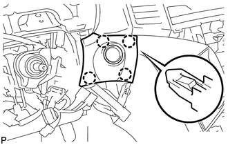
(b) Disconnect the connector and remove the lower instrument panel finish panel assembly.
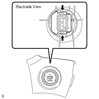
20. REMOVE ENGINE SWITCH
|
(a) Detach the 2 claws and remove the engine switch. |
|
 Inspection
INSPECTION
PROCEDURE
1. INSPECT ENGINE SWITCH
(a) Measure the resistance according to the value(s) in the table below.
Standard Resistance:
Tester Connection
Switch Condi ...
 Installation
INSTALLATION
PROCEDURE
1. INSTALL ENGINE SWITCH
(a) Attach the 2 claws to install the engine switch.
2. INSTALL LOWER INSTRUMENT PANEL FI ...
Other materials about Toyota Venza:
Touch Panel Switch does not Function
PROCEDURE
1.
CHECK MULTI-DISPLAY
(a) Check if there is any foreign matter caught between the display and exterior
frame of the multi-display.
OK:
No foreign matter is caught between the display and exterior frame of the m ...
How To Proceed With Troubleshooting
CAUTION / NOTICE / HINT
HINT:
Use the following procedure to troubleshoot the intuitive parking assist
system.
*: Use the Techstream.
PROCEDURE
1.
VEHICLE BROUGHT TO WORKSHOP
NEXT ...
Data List / Active Test
DATA LIST / ACTIVE TEST
HINT:
Using the Techstream to read the Data List allows the values or states of switches,
sensors, actuators and other items to be read without removing any parts. This non-intrusive
inspection can be very useful because intermitt ...

0.1267