Toyota Venza: Components
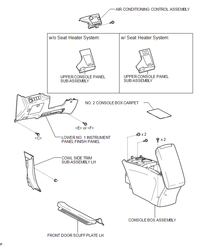
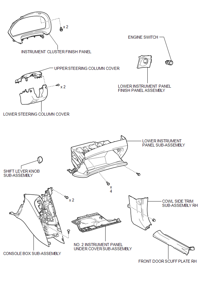
COMPONENTS
ILLUSTRATION
ILLUSTRATION
 Engine Switch
...
 Inspection
INSPECTION
PROCEDURE
1. INSPECT ENGINE SWITCH
(a) Measure the resistance according to the value(s) in the table below.
Standard Resistance:
Tester Connection
Switch Condi ...
Other materials about Toyota Venza:
Short in Side Squib LH Circuit (B1825/56-B1828/56)
DESCRIPTION
The side squib LH circuit consists of the center airbag sensor assembly and front
seat side airbag assembly LH.
The center airbag sensor assembly uses this circuit to deploy the airbag when
deployment conditions are met.
These DTCs are store ...
Precaution
PRECAUTION
NOTICE:
When disconnecting the cable from the negative (-) battery terminal, initialize
the following systems after the cable is reconnected.
System Name
See Procedure
Back Door Closer System
...
Power Source Control ECU Malfunction (B2782)
DESCRIPTION
The power management control ECU controls the power supply to activate the steering
lock motor. This prevents the steering wheel from being locked while the vehicle
is moving.
DTC No.
DTC Detecting Condition
T ...

0.1525