Toyota Venza: Inner Rear View Mirror Power Source Circuit
DESCRIPTION
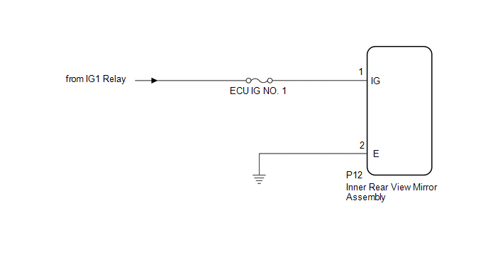
This circuit detects the state of the ignition switch, and sends it to the inner rear view mirror assembly.
WIRING DIAGRAM
CAUTION / NOTICE / HINT
NOTICE:
Inspect the fuses for circuits related to this system before performing the following inspection procedure.
PROCEDURE
|
1. |
CHECK HARNESS AND CONNECTOR (BATTERY - INNER REAR VIEW MIRROR ASSEMBLY) |
|
(a) Disconnect the P12 inner rear view mirror assembly connector. |
|
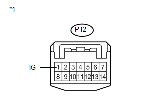
(b) Measure the voltage according to the value(s) in the table below.
Standard Voltage:
|
Tester Connection |
Switch Condition |
Specified Condition |
|---|---|---|
|
P12-1 (IG) - Body ground |
Ignition switch ON |
11 to 14 V |
|
Ignition switch off |
Below 1 V |
|
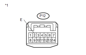
*1 |
Front view of wire harness connector (to Inner Rear View Mirror Assembly) |
| NG | .gif) |
REPAIR OR REPLACE HARNESS OR CONNECTOR |
|
.gif)
|
2. |
CHECK HARNESS AND CONNECTOR (INNER REAR VIEW MIRROR ASSEMBLY - BODY GROUND) |
|
(a) Measure the resistance according to the value(s) in the table below. Standard Resistance:
|
|
| OK | |
PROCEED TO NEXT SUSPECTED AREA SHOWN IN PROBLEM SYMPTOMS TABLE |
| NG | |
REPAIR OR REPLACE HARNESS OR CONNECTOR |
 Speed Signal Circuit
DESCRIPTION
The headlight leveling ECU assembly receives the vehicle speed signal from the
combination meter assembly.
HINT:
A voltage of 12 V or 5 V is output from each ECU and then inpu ...
 LVL Terminal Circuit
DESCRIPTION
By connecting terminals LVL and CG of the DLC3, the headlight leveling
ECU assembly initializes the height control sensor signal.
WIRING DIAGRAM
PROCEDURE
...
Other materials about Toyota Venza:
Engine Immobiliser System Malfunction (B2799)
DESCRIPTION
This DTC is stored when one of the following occurs: 1) the ECM detects an error
in its own communication with the certification ECU (smart key ECU assembly); 2)
the ECM detects an error in the communication lines; or 3) the ECU communication ...
Back Door Closer does not Operate
DESCRIPTION
When the back door closer does not operate, one of the following may be the cause:
1) improper fit of the back door, or a foreign object is stuck in the back door
or 2) initialization of the power back door ECU (power back door motor unit)*1, ...
Cruise control
Use the cruise control to maintain a set speed without depressing the accelerator
pedal.
1. Indicators
2. Cruise control switch
- Set the vehicle speed
Press the “ON-OFF” button to activate the cruise control.
Cruise control indicator will ...

0.1265