Toyota Venza: Speed Signal Circuit
DESCRIPTION
The headlight leveling ECU assembly receives the vehicle speed signal from the combination meter assembly.
HINT:
- A voltage of 12 V or 5 V is output from each ECU and then input to the combination meter. The signal is changed to a pulse signal at the transistor in the combination meter. Each ECU controls the respective system based on the pulse signal.
- If a short occurs in any of the ECUs or in the wire harness connected to an ECU, all systems in the diagram below will not operate normally.
WIRING DIAGRAM
1. for 2GR-FE
.png)
2. for 1AR-FE
.png)
PROCEDURE
|
1. |
CHECK COMBINATION METER SYSTEM |
(a) The circuits that send vehicle speed signals to this system are inspected
in the meter section (See page .gif) ).
).
(b) During inspection for the meter system, if there is an instruction that indicates to go back to inspections for the lighting system, proceed to the next step.
|
.gif)
|
2. |
CHECK HARNESS AND CONNECTOR (HEADLIGHT LEVELING ECU ASSEMBLY - COMBINATION METER ASSEMBLY) |
|
(a) Disconnect the E1 combination meter assembly connector. |
|
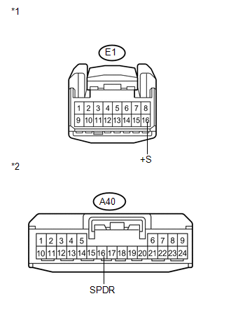
(b) Disconnect the A40 headlight leveling ECU assembly connector.
(c) Measure the resistance according to the value(s) in the table below.
Standard Resistance:
|
Tester Connection |
Condition |
Specified Condition |
|---|---|---|
|
A40-16 (SPDR) - E1-16 (+S) |
Always |
Below 1 Ω |
|
*1 |
Front view of wire harness connector (to Combination Meter Assembly) |
|
*2 |
Front view of wire harness connector (to Headlight Leveling ECU Assembly) |
| NG | .gif) |
REPAIR OR REPLACE HARNESS OR CONNECTOR (WIPER RELAY - COMBINATION METER) |
|
|
3. |
INSPECT COMBINATION METER ASSEMBLY (OUTPUT WAVEFORM) |
|
(a) Check the output waveform. (1) Remove the combination meter assembly with the connector still connected. (2) Connect an oscilloscope to terminal E1-16 (+S) and body ground. (3) Turn the ignition switch to ON. (4) Check the signal waveform according to the condition(s) in the table below.
OK: The waveform is displayed as shown in the illustration. Text in Illustration
HINT: When the system is functioning normally, one wheel revolution generates 4 pulses. As the vehicle speed increases, the width indicated by (A) in the illustration narrows. |
|
.png)
| OK | |
PROCEED TO NEXT SUSPECTED AREA SHOWN IN PROBLEM SYMPTOMS TABLE |
| NG | |
REPLACE COMBINATION METER ASSEMBLY |
 Indicator Circuit
DESCRIPTION
The headlight beam level control system indicator light in the combination meter
assembly comes on for approximately 3 seconds when the ignition switch is turned
to ON. The indicator ...
 Inner Rear View Mirror Power Source Circuit
DESCRIPTION
This circuit detects the state of the ignition switch, and sends it to the inner
rear view mirror assembly.
WIRING DIAGRAM
CAUTION / NOTICE / HINT
NOTICE:
Inspect the fuses for ci ...
Other materials about Toyota Venza:
Moon roof
Use the overhead switches to open, close, and tilt the moon roof up and down.
- Opening and closing
1. Open
The moon roof stops slightly before the fully open position to reduce wind noise.
Move the switch backward again to fully open.
2. Close ( ...
Inspection
INSPECTION
PROCEDURE
1. INSPECT SHIFT SOLENOID VALVE SL
(a) Measure the resistance according to the value(s) in the table below.
Text in Illustration
*1
Shift Solenoid Valve SL
Standard Re ...
Installation
INSTALLATION
PROCEDURE
1. INSTALL REAR SEAT INNER BELT ASSEMBLY RH
(a) Install the rear seat inner belt assembly RH with the bolt.
Torque:
42 N·m {428 kgf·cm, 31 ft·lbf}
2. INSTALL REAR SE ...

0.121