Toyota Venza: Reassembly
REASSEMBLY
PROCEDURE
1. INSTALL NO. 14 ROOF SILENCER PAD
(a) Align the markings on the roof headlining assembly with the No. 14 roof silencer pad and install the silencer pad using hot-melt glue as shown in the illustration.
.png)
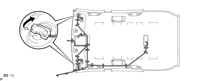
2. INSTALL NO. 1 ROOF WIRE (w/o Sliding Roof)
(a) Install the No. 1 roof wire.
 Text in Illustration
|
*1 |
Adhesive Tape |
- |
- |
(b) Turn the visor connectors clockwise approximately 90° to install the connectors to the roof headlining assembly.
(c) Apply adhesive tape to the locations shown in the illustration.
HINT:
As shown in the illustration, line up and secure the reference tape of the wire harness to the tip of the roof headlining assembly.
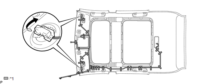
3. INSTALL NO. 1 ROOF WIRE (w/ Sliding Roof)
(a) Install the No. 1 roof wire.
 Text in Illustration
|
*1 |
Adhesive Tape |
- |
- |
(b) Turn the visor connectors clockwise approximately 90° to install the connectors to the roof headlining assembly.
(c) Apply adhesive tape to the locations shown in the illustration.
HINT:
As shown in the illustration, line up and secure the reference tape of the wire harness to the tip of the roof headlining assembly.
4. INSTALL NO. 2 ROOF SILENCER PAD (w/o Sliding Roof)
(a) Align the markings on the roof headlining assembly with the 2 No. 2 roof silencer pads and install the silencer pad using hot-melt glue or double-sided tape as shown in the illustration.
.png)
5. INSTALL NO. 3 ROOF SILENCER PAD (w/o Sliding Roof)
(a) Align the markings on the roof headlining assembly with the 3 No. 3 roof silencer pads and install the silencer pad using hot-melt glue or double-sided tape as shown in the illustration.
.png)
6. INSTALL FRONT SIDE RAIL SPACER LH (w/o Sliding Roof)
(a) Align the markings on the roof headlining assembly with the roof side rail spacer LH and install the spacer using hot-melt glue as shown in the illustration.
7. INSTALL FRONT SIDE RAIL SPACER RH (w/o Sliding Roof)
HINT:
Use the same procedure for the RH side and the LH side.
8. INSTALL VANITY LIGHT ASSEMBLY
(a) Install the vanity light assembly (See page
.gif) ).
).
HINT:
Use the same procedure for the RH side and the LH side.
9. INSTALL NO. 2 ANTENNA CORD SUB-ASSEMBLY (w/o Sliding Roof)
10. INSTALL NO. 2 ANTENNA CORD SUB-ASSEMBLY (w/ Sliding Roof)
 Removal
REMOVAL
PROCEDURE
1. REMOVE FRONT DOOR SCUFF PLATE LH
(a) Disengage the 3 clips, 7 claws and guide, and remove the front door
scuff plate LH.
...
 Installation
INSTALLATION
PROCEDURE
1. INSTALL ROOF HEADLINING ASSEMBLY (w/o Sliding Roof)
(a) Pull the roof headlining assembly into the vehicle through the back
door.
NOTICE:
Do not damag ...
Other materials about Toyota Venza:
Back Door Lock
Components
COMPONENTS
ILLUSTRATION
Removal
REMOVAL
PROCEDURE
1. REMOVE BACK DOOR PANEL TRIM ASSEMBLY
2. REMOVE BACK DOOR LOCK ASSEMBLY
(a) Disconnect the connector.
(b) Disengage the c ...
Installation
INSTALLATION
PROCEDURE
1. INSTALL CONSOLE BOX ASSEMBLY
(a) Connect the connectors.
(b) Engage the 2 claws.
(c) Install the screw and 2 clips.
...
Installation
INSTALLATION
PROCEDURE
1. INSTALL REAR DOOR COURTESY LIGHT SWITCH
(a) Using "TORX" socket wrench T30, install the rear door courtesy light
switch with the "TORX" bolt.
Torque:
8.0 N·m {82 kgf·cm, 71 in·lbf}
...

0.138