Toyota Venza: Ignition Coil And Spark Plug
Components
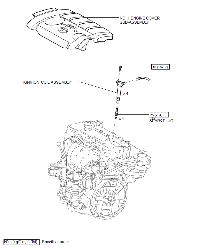
COMPONENTS
ILLUSTRATION
Removal
REMOVAL
PROCEDURE
1. REMOVE NO. 1 ENGINE COVER SUB-ASSEMBLY
.gif)
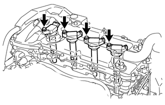
2. REMOVE IGNITION COIL ASSEMBLY
(a) Disconnect the 4 ignition coil assembly connectors.
|
(b) Remove the 4 bolts and 4 ignition coil assemblies. |
|
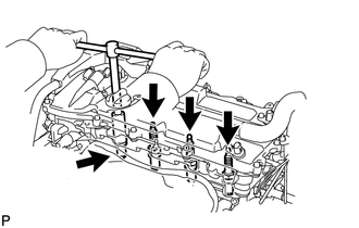
3. REMOVE SPARK PLUG
|
(a) Using a spark plug wrench, remove the 4 spark plugs. |
|
Installation
INSTALLATION
PROCEDURE
1. INSTALL SPARK PLUG
|
(a) Using a spark plug wrench, install the 4 spark plugs. Torque: 25 N·m {254 kgf·cm, 18 ft·lbf} HINT: Perform "Inspection After Repair" after replacing the spark plugs (See
page |
|
.png)
2. INSTALL IGNITION COIL ASSEMBLY
|
(a) Install the 4 ignition coil assemblies with the 4 bolts. Torque: 10 N·m {102 kgf·cm, 7 ft·lbf} HINT: Perform "Inspection After Repair" after replacing an ignition coil assembly
(See page |
|
.png)
(b) Connect the 4 ignition coil assembly connectors.
3. INSTALL NO. 1 ENGINE COVER SUB-ASSEMBLY
.gif)
 Heated Oxygen Sensor
Components
COMPONENTS
ILLUSTRATION
Removal
REMOVAL
PROCEDURE
1. REMOVE NO. 1 ENGINE UNDER COVER
2. REMOVE NO. 2 ENGINE UNDER COVER
3. REMOVE FRONT EXHAUST PIPE ASSEMBLY
4. REMOVE HEA ...
 Ignition System
...
Other materials about Toyota Venza:
Steering Lock Motor Drive Power Circuit
DESCRIPTION
The steering lock ECU (steering lock actuator assembly) is connected to the power
management control ECU. The steering lock ECU (steering lock actuator assembly)
cannot activate the motor unless it receives permission signals from both ECUs.
...
Power Mirror Surface Position is not Memorized
SYSTEM DESCRIPTION
If either the M1 or M2 seat memory switch is pressed, the outer mirror control
ECU assembly (driver door) detects the switch operation and sends the seat memory
switch signal to the main body ECU (driver side junction block assembly) vi ...
Removal
REMOVAL
PROCEDURE
1. REMOVE ENGINE OIL LEVEL DIPSTICK GUIDE
(a) Remove the engine oil level dipstick.
(b) Remove the bolt and engine oil level dipstick guide.
(c) Remove the O-ring from the engine ...

0.119