Toyota Venza: Heated Oxygen Sensor
Components
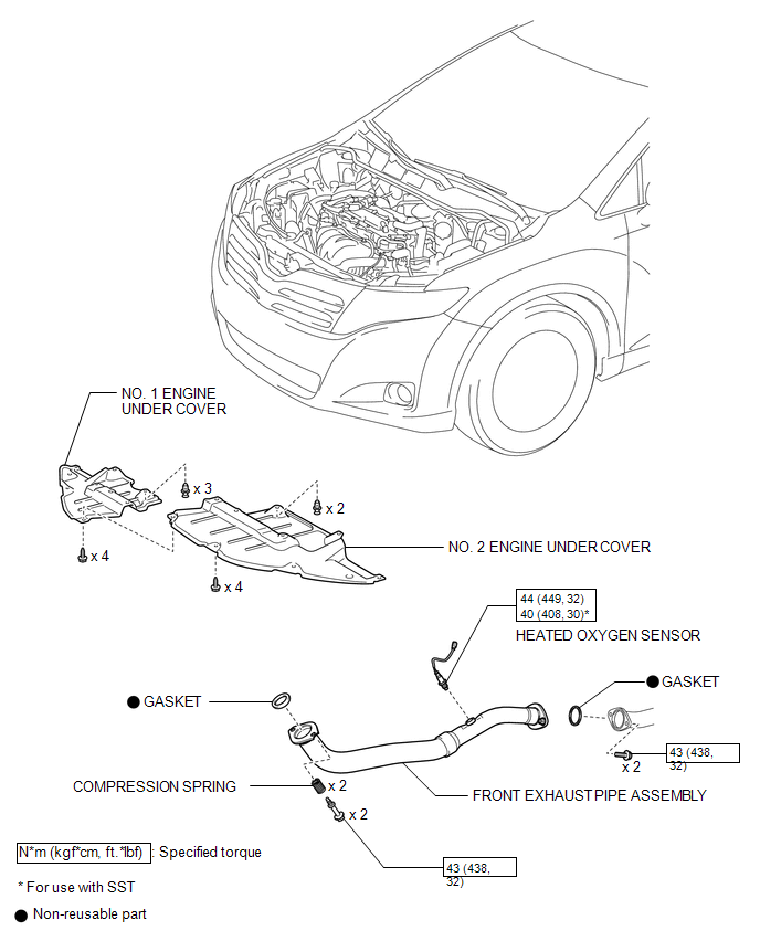
COMPONENTS
ILLUSTRATION
Removal
REMOVAL
PROCEDURE
1. REMOVE NO. 1 ENGINE UNDER COVER
2. REMOVE NO. 2 ENGINE UNDER COVER
3. REMOVE FRONT EXHAUST PIPE ASSEMBLY
.gif)
4. REMOVE HEATED OXYGEN SENSOR
|
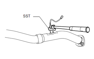
(a) Using SST, remove the heated oxygen sensor from the front exhaust pipe assembly. SST: 09224-00011 |
|
Inspection
INSPECTION
PROCEDURE
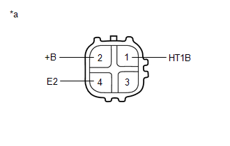
1. INSPECT HEATED OXYGEN SENSOR
|
(a) Measure the resistance according to the value(s) in the table below. Text in Illustration
Standard Resistance:
If the result is not as specified, replace the heated oxygen sensor. |
|
Installation
INSTALLATION
PROCEDURE
1. INSTALL HEATED OXYGEN SENSOR
HINT:
Perform "Inspection After Repair" after replacing the heated oxygen sensor (See
page .gif) ).
).
|
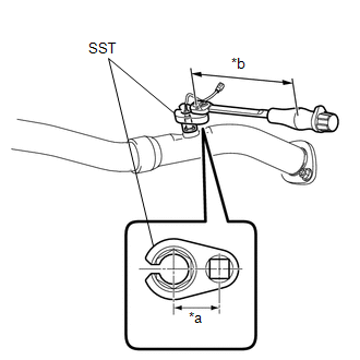
(a) Using SST, install the heated oxygen sensor to the front exhaust pipe assembly. Text in Illustration
SST: 09224-00011 Torque: without SST [Torque (N*m (kgf*cm, ft.*lbf))] : 44 N·m {449 kgf·cm, 32 ft·lbf} with SST [Reading of Torque wrench (N*m (kgf*cm, ft.*lbf))] : 40 N·m {408 kgf·cm, 30 ft·lbf} NOTICE: If the heated oxygen sensor has been struck or dropped, replace it. HINT:
|
|
2. INSTALL FRONT EXHAUST PIPE ASSEMBLY
3. INSPECT FOR EXHAUST GAS LEAK
4. INSTALL NO. 2 ENGINE UNDER COVER
5. INSTALL NO. 1 ENGINE UNDER COVER
6. PERFORM INITIALIZATION
(a) Perform "Inspection After Repair" after replacing the heated oxygen sensor
(See page ).
 Installation
INSTALLATION
PROCEDURE
1. INSTALL ENGINE COOLANT TEMPERATURE SENSOR
(a) Install a new gasket to the sensor.
Text in Illustration
*1
New Gasket
...
 Ignition Coil And Spark Plug
Components
COMPONENTS
ILLUSTRATION
Removal
REMOVAL
PROCEDURE
1. REMOVE NO. 1 ENGINE COVER SUB-ASSEMBLY
2. REMOVE IGNITION COIL ASSEMBLY
(a) Disconnect the 4 ignition coil assembly con ...
Other materials about Toyota Venza:
Transmitter ID1 Operation Stop (C2111/11-C2114/14)
DESCRIPTION
The tire pressure warning valve and transmitter installed in each tire and wheel
assembly measures the tire pressures. The measured values are transmitted as radio
waves to the tire pressure warning antenna and receiver on the body and then se ...
Inspection
INSPECTION
PROCEDURE
1. INSPECT PRELOAD
(a) Secure the steering column assembly in a vise.
Text in Illustration
*1
Service Nut
*2
Steering Wheel Assembly Set Nut
...
Wireless Door Lock Buzzer
Components
COMPONENTS
ILLUSTRATION
Installation
INSTALLATION
PROCEDURE
1. INSTALL WIRELESS DOOR LOCK BUZZER
(a) Engage the clamp and install the wireless door lock buzzer.
(b) Connect the ...

0.1597