Toyota Venza: Camshaft Position Sensor "B" Circuit (Bank 1) (P0365,P0367,P0368)
DESCRIPTION
The camshaft position sensor (EV signal sensor) for the exhaust camshaft consists of a magnet and MRE (Magneto Resistance Element).
The exhaust camshaft has a timing rotor for the camshaft position sensor. When the camshaft rotates, changes occur in the air gaps between the timing rotor and MRE, which affects the magnet. As a result, the resistance of the MRE material fluctuates. The camshaft position sensor converts the camshaft rotation data to pulse signals, uses the pulse signals to determine the camshaft angle, and sends it to the ECM. Then the ECM uses this data to control fuel injection duration, injection timing and the Variable Valve Timing (VVT) system.
|
DTC No. |
DTC Detection Condition |
Trouble Area |
|---|---|---|
|
P0365 |
No exhaust camshaft position sensor signal for 5 seconds at an engine speed of 600 rpm or more (1 trip detection logic). |
|
|
P0367 |
The output voltage of the exhaust camshaft position sensor is below 0.3 V for 4 seconds (1 trip detection logic). |
|
|
P0368 |
The output voltage of the exhaust camshaft position sensor is higher than 4.7 V for 4 seconds (1 trip detection logic). |
|
HINT:
Reference: Inspection using an oscilloscope (See page
.gif) ).
).
MONITOR DESCRIPTION
If no signal is transmitted by the exhaust camshaft position sensor despite the camshaft revolving, or the rotation of the exhaust camshaft and the crankshaft is not synchronized, the ECM interprets this as a malfunction of the sensor.
Also, when the sensor output voltage remains at below 0.3 V, or higher than 4.7 V for 4 seconds or more, the ECM stores a DTC.
MONITOR STRATEGY
|
Related DTCs |
P0365: Exhaust Camshaft Position Sensor Verify Pulse Input P0367: Exhaust Camshaft Position Sensor Range Check (Low Voltage) P0368: Exhaust Camshaft Position Sensor Range Check (High Voltage) |
|
Required Sensors/Components (Main) |
Exhaust camshaft position sensor |
|
Required Sensors/Components (Related) |
Crankshaft position sensor |
|
Frequency of Operation |
Continuous |
|
Duration |
5 seconds: P0365 4 seconds: P0367, P0368 |
|
MIL Operation |
Immediate |
|
Sequence of Operation |
None |
TYPICAL ENABLING CONDITIONS
P0365: Exhaust Camshaft Position Sensor Verify Pulse Input|
Monitor runs whenever the following DTCs are not stored |
None |
|
All of the following conditions are met |
- |
|
Engine speed |
600 rpm or more |
|
Exhaust camshaft position sensor range check fail (P0367, P0368) |
Not detected |
|
Ignition switch |
ON |
|
Starter |
OFF |
|
Battery voltage |
8 V or higher |
|
Exhaust camshaft position sensor voltage |
0.3 to 4.7 V |
|
Monitor runs whenever the following DTCs are not stored |
None |
|
All of the following conditions are met |
- |
|
Starter |
OFF |
|
Ignition switch |
ON |
|
Time after ignition switch off to ON |
2 seconds or more |
|
Exhaust camshaft position sensor pulse input fail (P0365) |
Not detected |
|
Battery voltage |
8 V or higher |
TYPICAL MALFUNCTION THRESHOLDS
P0365: Exhaust Camshaft Position Sensor Verify Pulse Input|
Exhaust camshaft position signal |
No signal |
|
Exhaust camshaft position sensor voltage |
Below 0.3 V |
|
Exhaust camshaft position sensor voltage |
Higher than 4.7 V |
COMPONENT OPERATING RANGE
|
Both of the following conditions are met |
- |
|
Exhaust camshaft position sensor voltage |
0.3 to 4.7 V |
|
Exhaust camshaft position sensor signal |
Signal input |
CONFIRMATION DRIVING PATTERN
- Connect the Techstream to the DLC3.
- Turn the ignition switch to ON and turn the Techstream on.
- Clear the DTCs (even if no DTCs are stored, perform the clear DTC procedure)
(See page ).
- Turn the ignition switch off and wait for at least 30 seconds.
- Turn the ignition switch to ON and turn the Techstream on.
- Start the engine.
- Idle the engine for 10 seconds or more [A].
- Enter the following menus: Powertrain / Engine / Trouble Codes [B].
- Read the Pending DTCs.
HINT:
- If a pending DTC is output, the system is malfunctioning.
- If a pending DTC is not output, perform the following procedure.
- Enter the following menus: Powertrain / Engine / Utility / All Readiness.
- Input the DTC: P0365, P0367 or P0368.
- Check the DTC judgment result.
Techstream Display
Description
NORMAL
- DTC judgment completed
- System normal
ABNORMAL
- DTC judgment completed
- System abnormal
INCOMPLETE
- DTC judgment not completed
- Perform driving pattern after confirming DTC enabling conditions
N/A
- Unable to perform DTC judgment
- Number of DTCs which do not fulfill DTC preconditions has reached ECU memory limit
HINT:
- If the judgment result shows NORMAL, the system is normal.
- If the judgment result shows ABNORMAL, the system has a malfunction.
- If the judgment result shows INCOMPLETE or N/A, perform steps [A] and [B] again.
- If the test result is INCOMPLETE or N/A and no pending DTC is output,
perform a universal trip and check for permanent DTCs (See page
).
HINT:
- If a permanent DTC is output, the system is malfunctioning.
- If no permanent DTC is output, the system is normal.
WIRING DIAGRAM
Refer to DTC P0335 (See page ).
CAUTION / NOTICE / HINT
HINT:
- Read freeze frame data using the Techstream. The ECM records vehicle and driving condition information as freeze frame data the moment a DTC is stored. When troubleshooting, freeze frame data can help determine if the vehicle was moving or stationary, if the engine was warmed up or not, if the air fuel ratio was lean or rich, and other data from the time the malfunction occurred.
- If no problem is found through this diagnostic troubleshooting procedure, there may be a mechanical problem with the engine.
PROCEDURE
|
1. |
INSPECT CAMSHAFT POSITION SENSOR (FOR EXHAUST CAMSHAFT) (POWER SOURCE) |
|
(a) Disconnect the camshaft position sensor (for exhaust camshaft) connector. |
|
(b) Turn the ignition switch to ON.
(c) Measure the voltage according to the value(s) in the table below.
Standard Voltage:
|
Tester Connection |
Switch Condition |
Specified Condition |
|---|---|---|
|
B56-3 (VC2) - Body ground |
Ignition switch ON |
4.5 to 5.5 V |
|
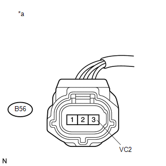
*a |
Front view of wire harness connector (to Camshaft Position Sensor (for Exhaust Camshaft)) |
| NG | .gif) |
GO TO STEP 8 |
|
.gif)
|
2. |
CHECK HARNESS AND CONNECTOR (CAMSHAFT POSITION SENSOR (FOR EXHAUST CAMSHAFT) - ECM) |
(a) Disconnect the camshaft position sensor (for exhaust camshaft) connector.
(b) Disconnect the ECM connector.
(c) Measure the resistance according to the value(s) in the table below.
Standard Resistance (Check for Open):
|
Tester Connection |
Condition |
Specified Condition |
|---|---|---|
|
B56-1 (VVE+) - B58-75 (EV1+) |
Always |
Below 1 Ω |
|
B56-2 (VVE-) - B58-121 (EV1-) |
Always |
Below 1 Ω |
Standard Resistance (Check for Short):
|
Tester Connection |
Condition |
Specified Condition |
|---|---|---|
|
B56-1 (VVE+) or B58-75 (EV1+) - Body ground |
Always |
10 kΩ or higher |
|
B56-2 (VVE-) or B58-121 (EV1-) - Body ground |
Always |
10 kΩ or higher |
| NG | |
REPAIR OR REPLACE HARNESS OR CONNECTOR |
|
|
3. |
CHECK SENSOR INSTALLATION (CAMSHAFT POSITION SENSOR (FOR EXHAUST CAMSHAFT)) |
(a) Check the camshaft position sensor (for exhaust camshaft) installation.
OK:
Sensor is installed correctly.
| NG | |
SECURELY REINSTALL SENSOR |
|
|
4. |
INSPECT EXHAUST CAMSHAFT (TIMING ROTOR) |
(a) Check the timing rotor of the exhaust camshaft.
OK:
Camshaft timing rotor does not have any cracks or deformation.
HINT:
Perform "Inspection After Repair" after replacing the exhaust camshaft (See page
).
| NG | |
REPLACE EXHAUST CAMSHAFT |
|
|
5. |
CHECK VALVE TIMING |
| NG | |
GO TO STEP 9 |
|
|
6. |
REPLACE CAMSHAFT POSITION SENSOR (FOR EXHAUST CAMSHAFT) |
(a) Replace the camshaft position sensor (for exhaust camshaft) (See page
).
|
|
7. |
CHECK WHETHER DTC OUTPUT RECURS (DTC P0365, P0367 OR P0368) |
(a) Connect the Techstream to the DLC3.
(b) Turn the ignition switch to ON.
(c) Turn the Techstream on.
(d) Clear the DTCs (See page ).
(e) Turn the ignition switch off and wait for at least 30 seconds.
(f) Start the engine and allow the engine to idle for 10 seconds or more.
(g) Enter the following menus: Powertrain / Engine / Trouble Codes.
(h) Read the DTCs.
|
Result |
Proceed to |
|---|---|
|
DTC P0365, P0367 or P0368 is output |
A |
|
DTC is not output |
B |
HINT:
If the engine does not start, replace the ECM.
| A | |
REPLACE ECM |
| B | |
END |
|
8. |
CHECK HARNESS AND CONNECTOR (CAMSHAFT POSITION SENSOR (FOR EXHAUST CAMSHAFT) - ECM) |
(a) Disconnect the camshaft position sensor (for exhaust camshaft) connector.
(b) Disconnect the ECM connector.
(c) Measure the resistance according to the value(s) in the table below.
Standard Resistance (Check for Open):
|
Tester Connection |
Condition |
Specified Condition |
|---|---|---|
|
B56-3 (VC2) - B58-98 (VCE1) |
Always |
Below 1 Ω |
Standard Resistance (Check for Short):
|
Tester Connection |
Condition |
Specified Condition |
|---|---|---|
|
B56-3 (VC2) or B58-98 (VCE1) - Body ground |
Always |
10 kΩ or higher |
| OK | |
REPLACE ECM |
| NG | |
REPAIR OR REPLACE HARNESS OR CONNECTOR |
|
9. |
CHECK ENGINE MECHANICAL SYSTEM |
| NG | |
REPAIR OR REPLACE MALFUNCTIONING PARTS, COMPONENT AND AREA |
|
|
10. |
CHECK WHETHER DTC OUTPUT RECURS |
(a) Connect the Techstream to the DLC3.
(b) Turn the ignition switch to ON.
(c) Turn the Techstream on.
(d) Clear the DTCs (See page ).
(e) Turn the ignition switch off and wait for at least 30 seconds.
(f) Start the engine and allow the engine to idle for 10 seconds or more.
(g) Enter the following menus: Powertrain / Engine / Trouble Codes.
(h) Read the DTCs.
|
Result |
Proceed to |
|---|---|
|
DTC P0365, P0367 or P0368 is output |
A |
|
DTC is not output |
B |
| A | |
REPLACE ECM |
| B | |
CHECK FOR INTERMITTENT PROBLEMS |
 Ignition Coil "A" Primary / Secondary Circuit (P0351-P0354)
DESCRIPTION
HINT:
These DTCs indicate malfunctions relating to the primary circuit.
If DTC P0351 is output, check the No. 1 ignition coil circuit.
If DTC P0352 is output, check th ...
 Catalyst System Efficiency Below Threshold (Bank 1) (P0420)
MONITOR DESCRIPTION
The ECM uses sensors mounted in front of and behind the Three-Way Catalytic Converter
(TWC) to monitor its efficiency.
The first sensor, the air fuel ratio sensor, sends pre-ca ...
Other materials about Toyota Venza:
Removal
REMOVAL
PROCEDURE
1. DISCHARGE FUEL SYSTEM PRESSURE
HINT:
See page
2. DISCONNECT CABLE FROM NEGATIVE BATTERY TERMINAL
NOTICE:
When disconnecting the cable, some systems need to be initialized after the cable
is reconnected (See page ).
3. REMOVE W ...
Lost Communication with A/C ECU (U0164)
DESCRIPTION
DTC No.
DTC Detection Condition
Trouble Area
U0164
No communication from the air conditioning amplifier continues.
Air conditioning amplifier branch wire or connect ...
Brake Line
Precaution
PRECAUTION
1. TROUBLESHOOTING PRECAUTION
NOTICE:
Since the brake lines are critical safety related parts, be sure to
disassemble and inspect the components if a brake fluid leak is found. If
any abnormality is found, replace th ...

0.1596