Toyota Venza: Entire Combination Meter does not Operate
DESCRIPTION
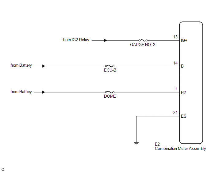
This circuit is the power source circuit for the meter. This circuit provides two types of power sources; one is a constant power source mainly used as a backup power source, and the other is an IG power source mainly used for signal transmission. The constant power source is mainly used as a backup power source for the meter CPU, however, it is also used for CAN communication. If a voltage of 12 V is not applied to terminal IG2 when the ignition switch is turned to ON, the indicator will not operate.
WIRING DIAGRAM
PROCEDURE
|
1. |
INSPECT COMBINATION METER ASSEMBLY |
|
(a) Disconnect the E2 connector. |
|
(b) Measure the resistance according to the value(s) in the table below.
Standard Resistance:
|
Tester Connection |
Condition |
Specified Condition |
|---|---|---|
|
E2-24 (ES) - Body ground |
Always |
Below 1 Ω |
(c) Measure the voltage according to the value(s) in the table below.
Standard Voltage:
|
Tester Connection |
Condition |
Specified Condition |
|---|---|---|
|
E2-13 (IG+) - Body ground |
Ignition switch ON |
11 to 14 V |
|
E2-1 (B2) - Body ground |
Always |
11 to 14 V |
|
E2-14 (B) - Body ground |
Always |
11 to 14 V |
|
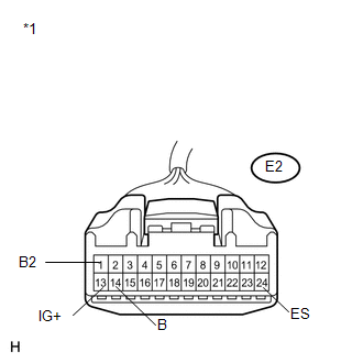
*1 |
Front view of wire harness connector (to Combination Meter Assembly) |
| OK | .gif) |
REPLACE COMBINATION METER ASSEMBLY |
| NG | |
REPAIR OR REPLACE HARNESS OR CONNECTOR |
 Lost Communication with ECM / PCM "A" (U0100,U0129)
DESCRIPTION
The combination meter assembly communicates with the ECM via the CAN communication
system (CAN No. 1 Bus).
DTC No.
DTC Detection Condition
Trouble Area ...
 Speedometer Malfunction
DESCRIPTION
The meter CPU receives vehicle speed signals from the skid control ECU via the
CAN communication system (CAN No. 1 Bus). The speed sensor detects the wheel speed
and sends the appropr ...
Other materials about Toyota Venza:
Installation
INSTALLATION
PROCEDURE
1. INSTALL NO. 1 COOLER THERMISTOR
2. INSTALL COOLER EVAPORATOR SUB-ASSEMBLY
3. INSTALL BLOWER ASSEMBLY WITH COOLER EVAPORATOR SUB-ASSEMBLY
(a) Engage the 5 claws.
(b) Engage the guide and connect the wire harness.
(c) Insta ...
Tire size
- Typical tire size information
The illustration indicates typical tire size.
1. Tire use
(P = Passenger car, T = Temporary use)
2. Section width (millimeters)
3. Aspect ratio
(tire height to section width)
4. Tire construction code
(R = Radial ...
How To Proceed With Troubleshooting
CAUTION / NOTICE / HINT
HINT:
Use the following procedure to troubleshoot the smart key system.
*: Use the Techstream.
PROCEDURE
1.
VEHICLE BROUGHT TO WORKSHOP
NEXT
...

0.145