Toyota Venza: Headlight Signal Circuit
DESCRIPTION
The headlight leveling ECU assembly detects the low beam headlights status.
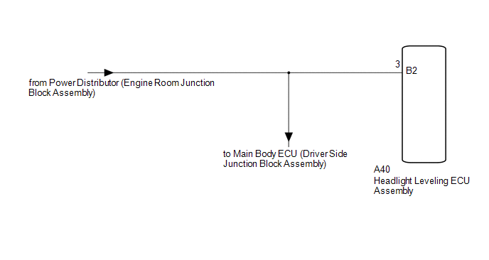
WIRING DIAGRAM
CAUTION / NOTICE / HINT
NOTICE:
First check that the low beam headlights operate normally.
PROCEDURE
|
1. |
CHECK HARNESS AND CONNECTOR (ENGINE ROOM JUNCTION BLOCK ASSEMBLY - ECU) |
|
(a) Disconnect the A40 headlight leveling ECU assembly connector. |
|
(b) Measure the voltage according to the value(s) in the table below.
Standard Voltage:
|
Tester Connection |
Switch Condition |
Specified Condition |
|---|---|---|
|
A40-3 (B2) - Body ground |
Light control switch in head position |
11 to 14 V |
|
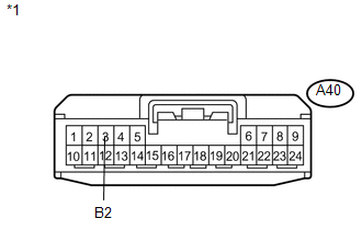
*1 |
Front view of wire harness connector (to Headlight Leveling ECU assembly) |
| OK | .gif) |
PROCEED TO NEXT SUSPECTED AREA SHOWN IN PROBLEM SYMPTOMS TABLE |
| NG | |
REPAIR OR REPLACE HARNESS OR CONNECTOR |
 Front Fog Light Circuit
DESCRIPTION
The main body ECU (driver side junction block assembly) controls the fog light
relay.
WIRING DIAGRAM
CAUTION / NOTICE / HINT
NOTICE:
Inspect the fuses for circuits related to this ...
 Light Control Switch Circuit
DESCRIPTION
The main body ECU (driver side junction block assembly) receives the following
switch information:
Light control switch position off, tail, head or AUTO
Dimmer switch positi ...
Other materials about Toyota Venza:
Installation
INSTALLATION
PROCEDURE
1. INSTALL NO. 1 ULTRASONIC SENSOR RETAINER
(a) Engage the 2 claws to install the No. 1 ultrasonic sensor retainer
to the rear bumper assembly.
Text in Illustration
*A
LH Side
...
Lost Communication with ECM / PCM "A" (U0100)
DESCRIPTION
The power management control ECU receives shift position information from 2 sources.
It receives a shift position P signal from the shift lock control unit assembly
via a direct line, and shift position information from the ECM via CAN. If the ...
Installation
INSTALLATION
CAUTION / NOTICE / HINT
HINT:
Use the same procedure for the RH side and LH side.
The procedure listed below is for the LH side.
PROCEDURE
1. INSTALL REAR AXLE CARRIER SUB-ASSEMBLY
(a) Temporarily install the rea ...

0.1526