
Toyota Venza: Have the vehicle inspected immediately.
Failing to investigate the cause of the following warnings may lead to the system operating abnormally and possibly cause an accident.
Have the vehicle inspected by your Toyota dealer immediately.
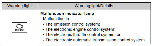
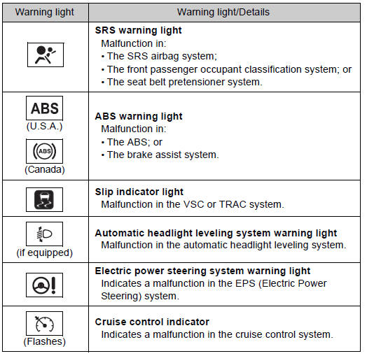
 Stop the vehicle immediately.
The following warning indicates the possibility of damage to the vehicle that
may lead to an accident. Immediately stop the vehicle in a safe place and contact
your Toyota dealer.
...
 Follow the correction procedures.
After taking the specified steps to correct the suspected problem, check that
the warning light turns off.
...
Other materials about Toyota Venza:
Disassembly
DISASSEMBLY
PROCEDURE
1. REMOVE TRANSMISSION WIRE
2. REMOVE ATF TEMPERATURE SENSOR ASSEMBLY
(a) Remove the 4 bolts, ATF temperature sensor assembly and clamp from
the valve body assembly.
Text in Illustration
*1
...
Evaporator Temperature Sensor Circuit (B1413/13)
DESCRIPTION
The evaporator temperature sensor is installed on the evaporator in the air conditioning
unit to detect the cooled air temperature that has passed through the evaporator
and to control the air conditioning. It sends appropriate signals to the ...
Outer Rear View Mirror Cover
Components
COMPONENTS
ILLUSTRATION
Installation
INSTALLATION
PROCEDURE
1. INSTALL OUTER MIRROR COVER
(a) Engage the 7 claws to install the outer mirror cover.
2. INSTALL OUTER MIRROR
R ...

0.1163