Toyota Venza: Daytime Running Light Relay Circuit
DESCRIPTION
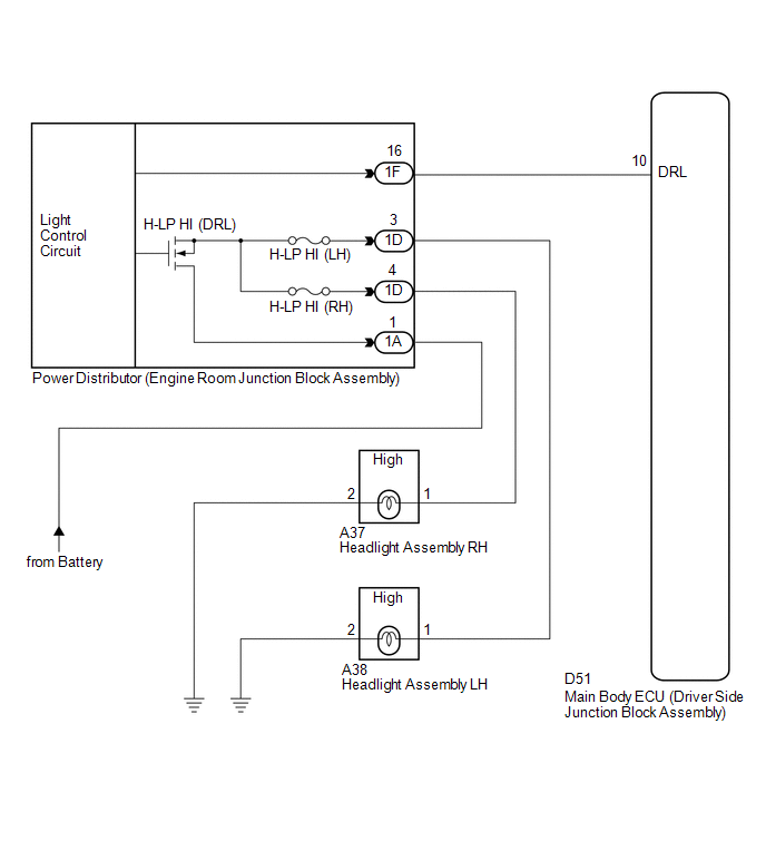
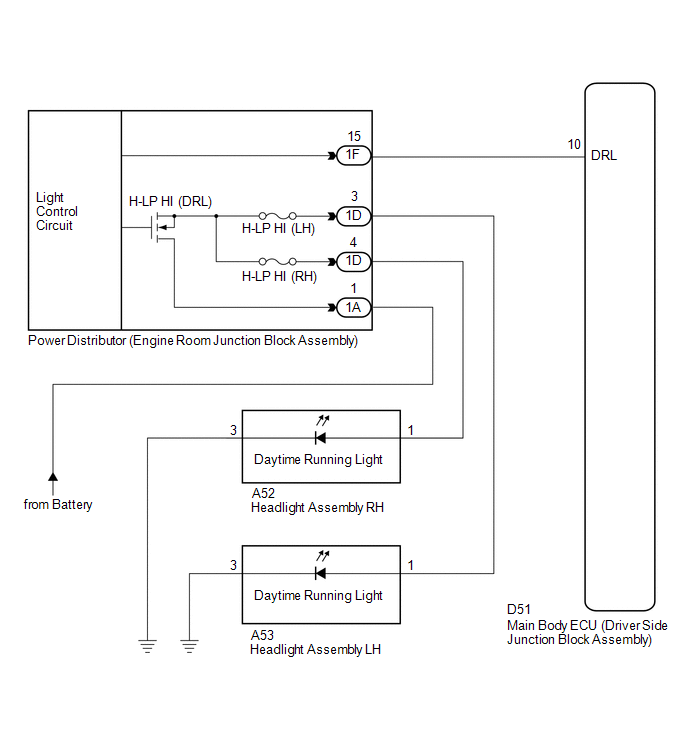
The main body ECU (driver side junction block assembly) controls the daytime running lights.
WIRING DIAGRAM
1. for Halogen Headlight
2. for HID Headlight
PROCEDURE
|
1. |
PERFORM ACTIVE TEST USING TECHSTREAM |
(a) Connect the Techstream to the DLC3.
(b) Turn the ignition switch to ON.
(c) Turn the Techstream on.
(d) Enter the following menus: Body Electrical / Main Body / Active Test.
(e) Check that the relay operates.
Main Body|
Tester Display |
Test Part |
Control Range |
Diagnostic Note |
|---|---|---|---|
|
Daytime Running Light |
Daytime running light relay |
ON/OFF |
- |
OK:
Relay operates. (Daytime running lights illuminate.)
|
Result |
Proceed to |
|---|---|
|
OK |
A |
|
NG (for Halogen Headlight) |
B |
|
NG (for HID Headlight) |
C |
| A | .gif) |
PROCEED TO NEXT SUSPECTED AREA SHOWN IN PROBLEM SYMPTOMS TABLE |
| C | |
GO TO STEP 5 |
|
.gif)
|
2. |
CHECK HEADLIGHT |
(a) Check the operation of the high beam headlights.
OK:
High beam headlights operate normally.
| NG | |
GO TO PROBLEM SYMPTOMS TABLE |
|
|
3. |
INSPECT POWER DISTRIBUTOR (ENGINE ROOM JUNCTION BLOCK ASSEMBLY) |
|
(a) Remove the power distributor (engine room junction block assembly)
from the engine room relay block (See page
|
|
.gif) ).
).
(b) Connect a positive (+) lead from the battery to terminal 1A-1.
(c) Connect a negative (-) lead from the battery to terminal 1F-16.
(d) Check for pulses according to the value(s) in the table below.
Standard:
|
Tester Connection |
Condition |
Specified Condition |
|---|---|---|
|
1D-3 - Battery negative |
Always |
Pulse generation |
|
1D-4 - Battery negative |
Always |
Pulse generation |
|
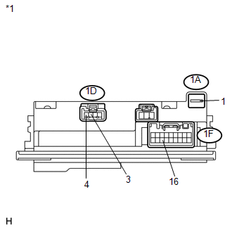
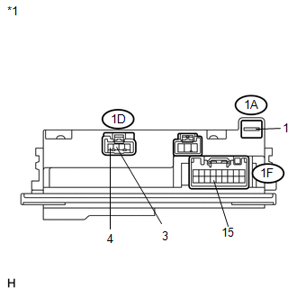
*1 |
Component without harness connected (Power Distributor (Engine Room Junction Block Assembly)) |
| NG | |
REPLACE POWER DISTRIBUTOR (ENGINE ROOM JUNCTION BLOCK ASSEMBLY) |
|
|
4. |
CHECK HARNESS AND CONNECTOR (ENGINE ROOM JUNCTION BLOCK ASSEMBLY - MAIN BODY ECU) |
|
(a) Disconnect the 1F power distributor (engine room junction block assembly) connector. |
|
(b) Disconnect the D51 main body ECU (driver side junction block assembly) connector.
(c) Measure the resistance according to the value(s) in the table below.
Standard Resistance:
|
Tester Connection |
Condition |
Specified Condition |
|---|---|---|
|
1F-16 - D51-10 (DRL) |
Always |
Below 1 Ω |
|
D51-10 (DRL) - Body ground |
Always |
10 kΩ or higher |
|
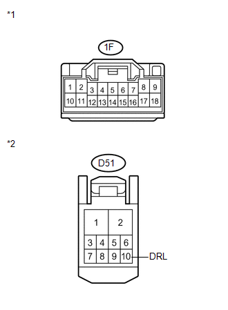
*1 |
Front view of wire harness connector (to Power Distributor (Engine Room Junction Block Assembly)) |
|
*2 |
Front view of wire harness connector (to Main Body ECU (Driver Side Junction Block Assembly)) |
| OK | |
REPLACE MAIN BODY ECU (DRIVER SIDE JUNCTION BLOCK ASSEMBLY) |
| NG | |
REPAIR OR REPLACE HARNESS OR CONNECTOR |
|
5. |
INSPECT POWER DISTRIBUTOR (ENGINE ROOM JUNCTION BLOCK ASSEMBLY) |
|
(a) Remove the power distributor (engine room junction block assembly)
from the engine room relay block (See page
|
|
(b) Connect a positive (+) lead from the battery to terminal 1A-1.
(c) Connect a negative (-) lead from the battery to terminal 1F-15.
(d) Check for pulses according to the value(s) in the table below.
Standard:
|
Tester Connection |
Condition |
Specified Condition |
|---|---|---|
|
1D-3 - Battery negative |
Always |
Pulse generation |
|
1D-4 - Battery negative |
Always |
Pulse generation |
|
*1 |
Component without harness connected (Power Distributor (Engine Room Junction Block Assembly)) |
| NG | |
REPLACE POWER DISTRIBUTOR (ENGINE ROOM JUNCTION BLOCK ASSEMBLY) |
|
|
6. |
CHECK HARNESS AND CONNECTOR (ENGINE ROOM JUNCTION BLOCK ASSEMBLY - MAIN BODY ECU) |
|
(a) Disconnect the 1F power distributor (engine room junction block assembly) connector. |
|
(b) Disconnect the D51 main body ECU (driver side junction block assembly) connector.
(c) Measure the resistance according to the value(s) in the table below.
Standard Resistance:
|
Tester Connection |
Condition |
Specified Condition |
|---|---|---|
|
1F-15 - D51-10 (DRL) |
Always |
Below 1 Ω |
|
D51-10 (DRL) - Body ground |
Always |
10 kΩ or higher |
|
*1 |
Front view of wire harness connector (to Power Distributor (Engine Room Junction Block Assembly)) |
|
*2 |
Front view of wire harness connector (to Main Body ECU (Driver Side Junction Block Assembly)) |
| OK | |
REPLACE MAIN BODY ECU (DRIVER SIDE JUNCTION BLOCK ASSEMBLY) |
| NG | |
REPAIR OR REPLACE HARNESS OR CONNECTOR |
 Headlight Solenoid Circuit
DESCRIPTION
for HID Headlight:
When the main body ECU receives a high beam turn on signal, the main
body ECU activates the bi-function by controlling the BI-XENON relay. The
bi-func ...
 Headlight (HI-BEAM) Circuit
DESCRIPTION
for Halogen Headlight:
The main body ECU (driver side junction block assembly) controls the
high beam headlights.
WIRING DIAGRAM
CAUTION / NOTICE / HINT
NOTICE ...
Other materials about Toyota Venza:
Removal
REMOVAL
PROCEDURE
1. DISCONNECT CABLE FROM NEGATIVE BATTERY TERMINAL
CAUTION:
Wait at least 90 seconds after disconnecting the cable from the negative (-)
battery terminal to disable the SRS system.
NOTICE:
When disconnecting the cable, some systems ne ...
Engine Immobiliser System Malfunction (B2799)
DESCRIPTION
This DTC is stored when one of the following occurs: 1) the ECM detects errors
in its own communications with the transponder key ECU assembly; 2) the ECM detects
errors in the communication lines; or 3) the ECU communication ID between the tr ...
Inspection
INSPECTION
PROCEDURE
1. INSPECT STEERING PAD SWITCH ASSEMBLY
(a) Measure the resistance according to the value(s) in the table below.
Standard Resistance:
Tester Connection
Condition
Specified Condition
...

0.1141