Toyota Venza: Adjustment
ADJUSTMENT
PROCEDURE
1. ADJUST PARK/NEUTRAL POSITION SWITCH ASSEMBLY
(a) Remove the transmission control shaft lever.
HINT:
See the steps from "Remove Cool Air Intake Duct Seal" through "Remove Park/Neutral
Position Switch Assembly" (See page .gif) ).
).
|
(b) Loosen the 2 bolts of the park/neutral position switch. |
|
.png)
|
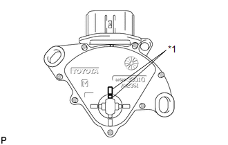
(c) Align the protrusions of the park/neutral position switch. Text in Illustration
|
|
|
(d) Hold the park/neutral position switch in position and tighten the 2 bolts. Torque: 5.4 N·m {55 kgf·cm, 48 in·lbf} NOTICE: After installing the park/neutral position switch, confirm that the 2 protrusions on the switch are aligned. |
|
(e) Install the transmission control shaft lever.
HINT:
See the steps from "Install Park/Neutral Position Switch Assembly" through "Install
Cool Air Intake Duct Seal" (See page ).
(f) After the adjustment, perform the switch operation check (See page
).
 Inspection
INSPECTION
PROCEDURE
1. INSPECT PARK/NEUTRAL POSITION SWITCH ASSEMBLY
(a) Measure the resistance according to the value(s) in the table below
when the shift lever is moved to each po ...
 Installation
INSTALLATION
PROCEDURE
1. INSTALL PARK/NEUTRAL POSITION SWITCH ASSEMBLY
(a) Move the shift lever to N.
(b) Align the protrusions of the park/neutral position switch.
Text in Illustra ...
Other materials about Toyota Venza:
Data List / Active Test
DATA LIST / ACTIVE TEST
1. DATA LIST
HINT:
Using the Techstream to read the Data List allows the values or states of switches,
sensors, actuators and other items to be read without removing any parts. This non-intrusive
inspection can be very useful bec ...
Reassembly
REASSEMBLY
PROCEDURE
1. INSTALL BEARING BRACKET HOLE SNAP RING (for RH Side)
(a) Install a new bearing bracket hole snap ring to the front drive shaft assembly
RH.
2. INSTALL FRONT DRIVE SHAFT BEARING (for RH Side)
(a) Using SST, install a ne ...
Disposal
DISPOSAL
CAUTION / NOTICE / HINT
CAUTION:
Before performing pre-disposal deployment of any SRS component, review and closely
follow all applicable environmental and hazardous material regulations. Pre-disposal
deployment may be considered hazardous mate ...

0.1177