Toyota Venza: Glove Box Light
Components
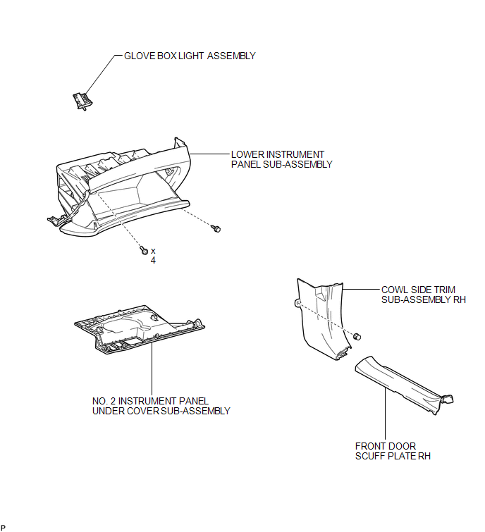
COMPONENTS
ILLUSTRATION
Inspection
INSPECTION
PROCEDURE
1. INSPECT GLOVE BOX LIGHT ASSEMBLY
|
(a) Connect a positive (+) lead from the battery to terminal 1 and a negative (-) lead to terminal 2. |
|
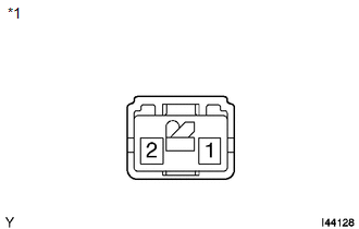
(b) Check that the light comes on when the glove box light switch is on (not pushed).
OK:
Glove box light comes on.
Text in Illustration|
*1 |
Component without harness connected (Glove Box Light Assembly) |
If the result is not as specified, replace the glove box light assembly.
Removal
REMOVAL
PROCEDURE
1. REMOVE FRONT DOOR SCUFF PLATE RH
HINT:
Use the same procedure for the RH side and LH side (See page
.gif) ).
).
2. REMOVE COWL SIDE TRIM SUB-ASSEMBLY RH
HINT:
Use the same procedure for the RH side and LH side (See page
).
3. REMOVE NO. 2 INSTRUMENT PANEL UNDER COVER SUB-ASSEMBLY
4. REMOVE LOWER INSTRUMENT PANEL SUB-ASSEMBLY
5. REMOVE GLOVE BOX LIGHT ASSEMBLY
|
(a) Disengage the 2 claws. |
|
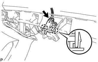
(b) Disconnect the connector and remove the glove box light assembly.
Installation
INSTALLATION
PROCEDURE
1. INSTALL GLOVE BOX LIGHT ASSEMBLY
|
(a) Connect the connector. |
|
.png)
(b) Engage the 2 claws to install the glove box light assembly.
2. INSTALL LOWER INSTRUMENT PANEL SUB-ASSEMBLY
.gif)
3. INSTALL NO. 2 INSTRUMENT PANEL UNDER COVER SUB-ASSEMBLY
4. INSTALL COWL SIDE TRIM SUB-ASSEMBLY RH
HINT:
Use the same procedure for the RH side and LH side (See page
).
5. INSTALL FRONT DOOR SCUFF PLATE RH
HINT:
Use the same procedure for the RH side and LH side (See page
).
 Front Door Courtesy Switch
Components
COMPONENTS
ILLUSTRATION
Inspection
INSPECTION
PROCEDURE
1. INSPECT COURTESY LIGHT SWITCH
(a) Measure the resistance according to the value(s) in the table below.
Standard Re ...
 Ignition Key Cylinder Light
Components
COMPONENTS
ILLUSTRATION
Inspection
INSPECTION
PROCEDURE
1. INSPECT TRANSPONDER KEY AMPLIFIER
(a) Connect a positive (+) lead from battery to terminal 2 and a negativ ...
Other materials about Toyota Venza:
All Doors LOCK/UNLOCK Functions do not Operate Via Door Control Switch
DESCRIPTION
The main body ECU (driver side junction block assembly) receives switch signals
from the door control switch and activates the door lock motor on each door according
to these signals.
WIRING DIAGRAM
PROCEDURE
1.
REA ...
Illumination for Panel Switch does not Come on with Tail Switch ON
PROCEDURE
1.
CHECK VEHICLE SIGNAL (OPERATION CHECK)
(a) Enter the "Vehicle Signal Check Mode" screen.
Refer to Check Vehicle Signal in Operation Check (See page
).
...
Problem Symptoms Table
PROBLEM SYMPTOMS TABLE
Use the table below to help determine the cause of problem symptoms.
If multiple suspected areas are listed, the potential causes of the symptoms
are listed in order of probability in the "Suspected Area" column ...

0.16