Toyota Venza: Front Door Courtesy Switch
Components
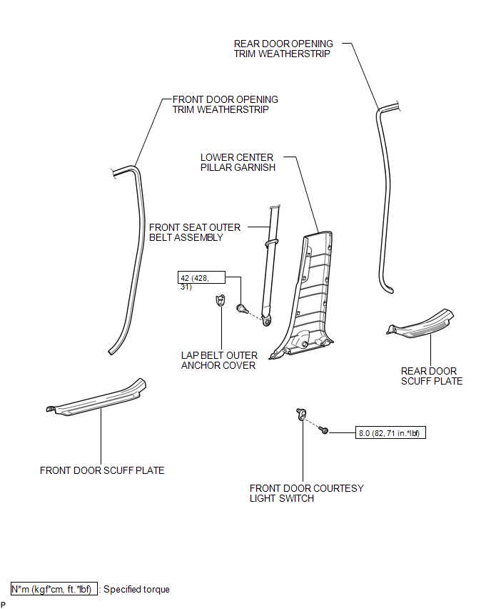
COMPONENTS
ILLUSTRATION
Inspection
INSPECTION
PROCEDURE
1. INSPECT COURTESY LIGHT SWITCH
(a) Measure the resistance according to the value(s) in the table below.
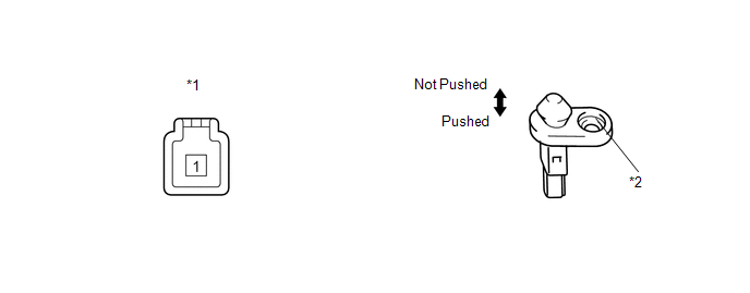
Standard Resistance:
|
Tester Connection |
Switch Condition |
Specified Condition |
|---|---|---|
|
1 - Switch body |
Pushed |
10 kΩ or higher |
|
1 - Switch body |
Not pushed |
Below 1 Ω |
|
*1 |
Component without harness connected (Courtesy Light Switch) |
*2 |
Switch Body |
If the result is not as specified, replace the courtesy light switch.
Removal
REMOVAL
PROCEDURE
1. REMOVE FRONT DOOR SCUFF PLATE
.gif)
2. DISCONNECT FRONT DOOR OPENING TRIM WEATHERSTRIP
3. REMOVE REAR DOOR SCUFF PLATE
4. DISCONNECT REAR DOOR OPENING TRIM WEATHERSTRIP
5. REMOVE LAP BELT OUTER ANCHOR COVER
6. DISCONNECT FRONT SEAT OUTER BELT ASSEMBLY
7. REMOVE LOWER CENTER PILLAR GARNISH
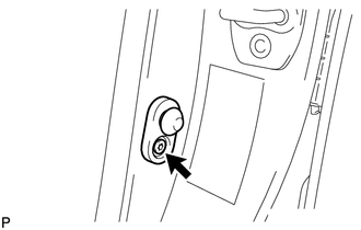
8. REMOVE FRONT DOOR COURTESY LIGHT SWITCH
(a) Disconnect the connector.
|
(b) Using "TORX" socket wrench T30, remove the "TORX" bolt and front door courtesy light switch. |
|
Installation
INSTALLATION
PROCEDURE
1. INSTALL FRONT DOOR COURTESY LIGHT SWITCH
|
(a) Using "TORX" socket wrench T30, install the front door courtesy light switch with the "TORX" bolt. Torque: 8.0 N·m {82 kgf·cm, 71 in·lbf} |
|
.png)
(b) Connect the connector.
2. INSTALL LOWER CENTER PILLAR GARNISH
.gif)
3. CONNECT FRONT SEAT OUTER BELT ASSEMBLY
4. INSTALL LAP BELT OUTER ANCHOR COVER
5. CONNECT REAR DOOR OPENING TRIM WEATHERSTRIP
6. INSTALL REAR DOOR SCUFF PLATE
7. CONNECT FRONT DOOR OPENING TRIM WEATHERSTRIP
8. INSTALL FRONT DOOR SCUFF PLATE
 Door Courtesy Light
Components
COMPONENTS
ILLUSTRATION
Removal
REMOVAL
PROCEDURE
1. REMOVE COURTESY LIGHT ASSEMBLY
(a) Using a screwdriver wrapped with protective tape, disengage the claw.
Text ...
 Glove Box Light
Components
COMPONENTS
ILLUSTRATION
Inspection
INSPECTION
PROCEDURE
1. INSPECT GLOVE BOX LIGHT ASSEMBLY
(a) Connect a positive (+) lead from the battery to terminal 1 and a
...
Other materials about Toyota Venza:
Disassembly
DISASSEMBLY
PROCEDURE
1. REMOVE STEERING RACK BOOT CLIP (for LH Side)
(a) Using pliers, remove the steering rack boot clip.
2. REMOVE STEERING RACK BOOT CLIP (for RH Side)
HINT:
Perform the same procedure as for the LH side.
3. REMOVE NO. 2 STEERING RAC ...
Adjustment
ADJUSTMENT
CAUTION / NOTICE / HINT
CAUTION:
Before adjusting the door positions of vehicles equipped with side and curtain
shield airbags, be sure to disconnect the battery. After adjustment, check that
the SRS warning light is operating normally and ...
Power Mirrors do not Return to Memorized Position
SYSTEM DESCRIPTION
If either the M1 or M2 seat memory switch is pressed, the outer mirror control
ECU assembly (driver door) detects the seat memory switch status and sends the switch
signal to the main body ECU (driver side junction block assembly) via C ...

0.1288