Toyota Venza: Ignition Key Cylinder Light
Components
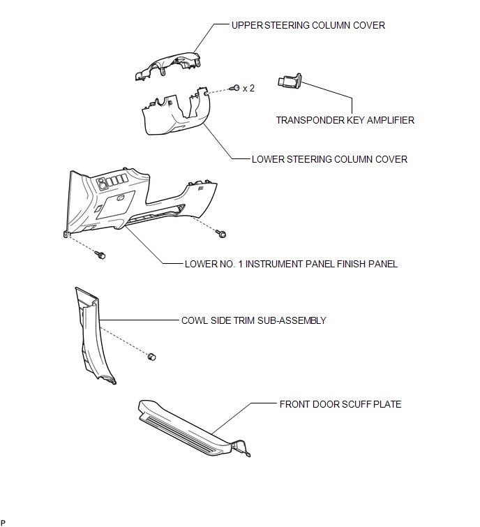
COMPONENTS
ILLUSTRATION
Inspection
INSPECTION
PROCEDURE
1. INSPECT TRANSPONDER KEY AMPLIFIER
|
(a) Connect a positive (+) lead from battery to terminal 2 and a negative (-) lead to terminal 6. |
|
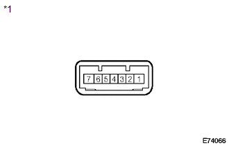
(b) Check that the light comes on.
OK:
The light comes on.
Text in Illustration|
*1 |
Component without harness connected (transponder key amplifier) |
If the result is not as specified, replace the transponder key amplifier.
Removal
REMOVAL
PROCEDURE
1. REMOVE FRONT DOOR SCUFF PLATE
.gif)
2. REMOVE COWL SIDE TRIM SUB-ASSEMBLY
3. REMOVE LOWER NO. 1 INSTRUMENT PANEL FINISH PANEL
4. REMOVE LOWER STEERING COLUMN COVER
5. REMOVE UPPER STEERING COLUMN COVER
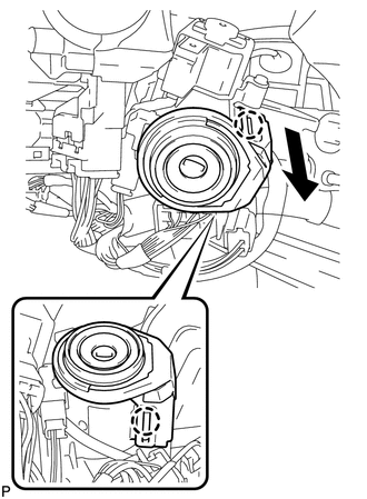
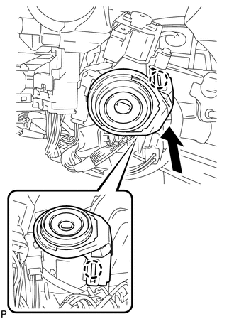
6. REMOVE TRANSPONDER KEY AMPLIFIER
|
(a) Disengage the 2 claws and disconnect the transponder key amplifier as shown in the illustration. |
|
|
(b) Disconnect the connector and remove the transponder key amplifier. |
|
Installation
INSTALLATION
PROCEDURE
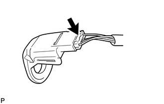
1. INSTALL TRANSPONDER KEY AMPLIFIER
|
(a) Connect the connector to the transponder key amplifier. |
|
.png)
|
(b) Engage the 2 claws and install the transponder key amplifier. |
|
2. INSTALL UPPER STEERING COLUMN COVER
.gif)
3. INSTALL LOWER STEERING COLUMN COVER
4. INSTALL LOWER NO. 1 INSTRUMENT PANEL FINISH PANEL
5. INSTALL COWL SIDE TRIM SUB-ASSEMBLY
6. INSTALL FRONT DOOR SCUFF PLATE
 Glove Box Light
Components
COMPONENTS
ILLUSTRATION
Inspection
INSPECTION
PROCEDURE
1. INSPECT GLOVE BOX LIGHT ASSEMBLY
(a) Connect a positive (+) lead from the battery to terminal 1 and a
...
 Lighting System
...
Other materials about Toyota Venza:
Diagnostic Trouble Code Chart
DIAGNOSTIC TROUBLE CODE CHART
HINT:
When the air conditioning system functions properly, DTC B1400/00 is output.
Air Conditioning System
DTC Code
Detection Item
Trouble Area
Memory*3
See page
...
Disassembly
DISASSEMBLY
PROCEDURE
1. REMOVE BRAKE PEDAL RETURN SPRING
(a) Remove the brake pedal return spring from the brake pedal support
assembly.
2. REMOVE BRAKE PEDAL PAD
(a) Remove the brake pedal pa ...
On-vehicle Inspection
ON-VEHICLE INSPECTION
PROCEDURE
1. INSPECT REFRIGERANT PRESSURE WITH MANIFOLD GAUGE SET
HINT:
This is a method where a manifold gauge set is used to help locate the problem.
(a) Read the manifold gauge pressure when the following conditions are met:
Test ...

0.1422