Toyota Venza: Reassembly
REASSEMBLY
PROCEDURE
1. INSTALL AIR OUTLET CONTROL SERVO MOTOR SUB-ASSEMBLY
|
(a) Check that the slots, links and gears of the air outlet control servo motor sub-assembly are positioned in the correct orientation as shown in the illustration. |
|
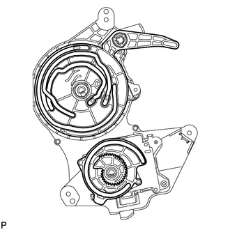
(b) Face the contact surfaces of the air outlet control servo motor sub-assembly and air conditioning radiator assembly for the air outlet control servo motor sub-assembly upward.
(c) Rotate the link of the air conditioning radiator assembly all the way to the left as shown in the illustration.
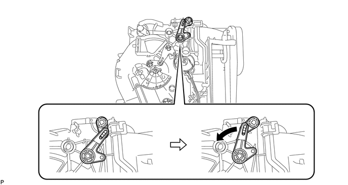
(d) Rotate the link of the air conditioning radiator assembly to the bottom as shown in the illustration and confirm that the mode switching duct hole is fully closed.
 Text in Illustration
|
*a |
Mode Switching Duct Hole |
- |
- |
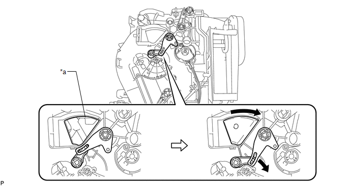
(e) Rotate the lever of the air conditioning radiator assembly to the top as shown in the illustration.
(f) Rotate the link of the air conditioning radiator assembly to the in-line position as shown in the illustration.
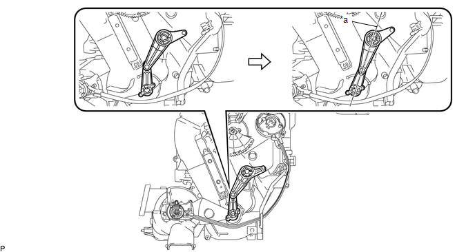 Text in Illustration
|
*a |
In-line Position |
- |
- |
|
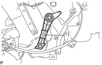
(g) Wrap the upper and lower links with vinyl tape to hold them in the in-line position. Text in Illustration
|
|
(h) Install the link of the air outlet control servo motor sub-assembly to the link guide pin (A) of the air conditioning radiator assembly as shown in the illustration.
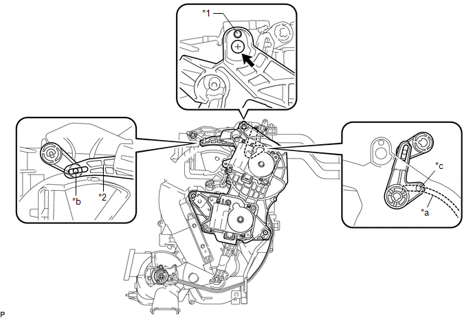 Text in Illustration
|
*1 |
Guide |
*2 |
Air Outlet Control Servo Motor Sub-assembly |
|
*a |
Air Outlet Control Servo Motor Sub-assembly Slot |
*b |
Link Guide Pin (A) |
|
*c |
Link Guide Pin (B) |
- |
- |
(i) Install the guide hole of the air outlet control servo motor sub-assembly to the guide pin of the air conditioning radiator assembly as shown in the illustration.
(j) Temporarily install the screw (up to 4 or 5 threads).
NOTICE:
- Make sure that the link guide pin (B) is inserted in the air conditioning radiator assembly slot.
- Avoid tilting the air conditioning radiator assembly during installation. This helps to prevent the guide pins from coming out of position.
|
(k) Lift the air outlet control servo motor sub-assembly slightly to create clearance. |
|
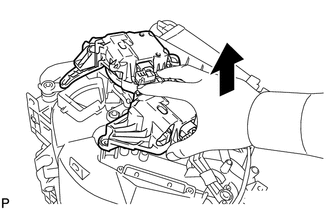
(l) Move the air conditioning radiator assembly gear so that alignment holes of the air outlet control servo motor sub-assembly and air conditioning radiator assembly are aligned.
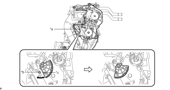 Text in Illustration
|
*a |
Air Outlet Control Servo Motor Sub-assembly Alignment Hole |
*b |
Air Conditioning Radiator Assembly Alignment Hole |
|
*c |
Air Conditioning Radiator Assembly Gear Alignment Hole |
- |
- |
|
(m) Insert a screwdriver into the aligned holes as shown in the illustration. |
|
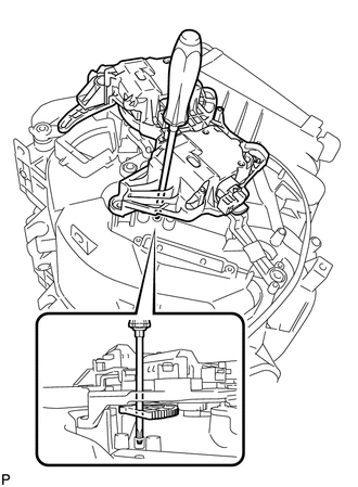
(n) Make sure that all the links and gears are in the positions shown in the illustration.
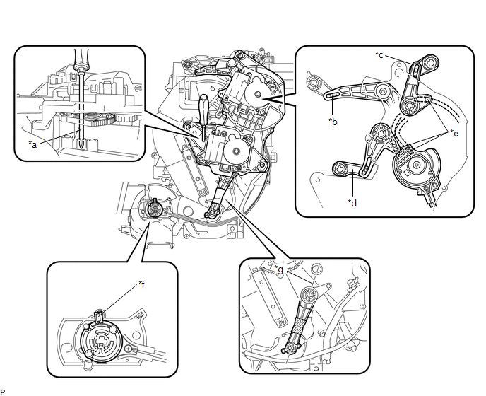 Text in Illustration
|
*a |
Screwdriver is inserted into alignment holes. |
*b |
Link guide pin is inserted. |
|
*c |
Links is positioned to left side. |
*d |
Links is positioned at bottom. |
|
*e |
Each link guide pin is inserted in its air outlet control servo motor sub-assembly slot. |
*f |
Lever is positioned at top. |
|
*g |
Links are in-line. |
- |
- |
|
(o) Push the loose fitting air outlet control servo motor sub-assembly into position. NOTICE:
HINT: Push the air outlet control servo motor sub-assembly until a click sound is heard. |
|
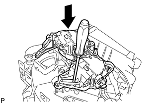
(p) Remove the screwdriver.
|
(q) Fully install the top screw, and then install the air outlet control servo motor sub-assembly with the 2 remaining screws. |
|
(r) Remove the vinyl tape.
2. INSTALL HEATER RADIATOR UNIT SUB-ASSEMBLY
|
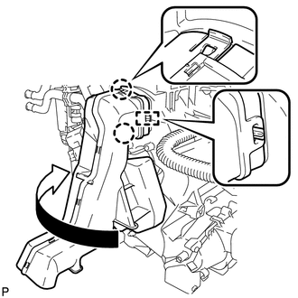
(a) Install the heater radiator unit sub-assembly as shown in the illustration. |
|
|
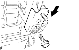
(b) Install the clamp with the screw. Text in Illustration
|
|
.png)
(c) Engage the 3 claws to install the heater clamp.
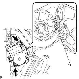
3. INSTALL AIR MIX CONTROL SERVO MOTOR SUB-ASSEMBLY
|
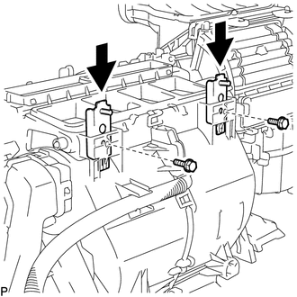
(a) Using the reference point, install the air mix control servo motor sub-assembly with the 2 screws. Text in Illustration
|
|
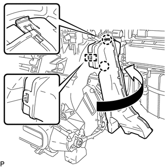
4. INSTALL ASPIRATOR PIPE
|
(a) Engage the 2 claws and clamp to install the aspirator pipe. |
|
.png)
5. INSTALL NO. 1 COOLER THERMISTOR
.gif)
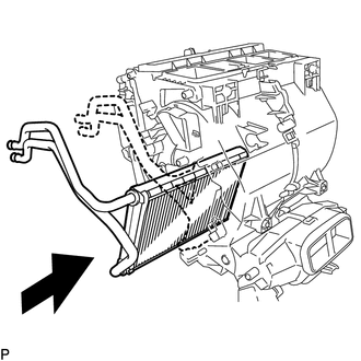
6. INSTALL COOLER EVAPORATOR SUB-ASSEMBLY
(a) Sufficiently apply compressor oil to 2 new O-rings and the fitting surfaces.
Compressor oil:
ND-OIL 8 or equivalent
|
(b) Install the 2 O-rings to the cooler evaporator sub-assembly. NOTICE: Keep the O-rings and O-ring fitting surfaces free from dirt or any foreign objects. |
|
.png)
|
(c) Engage the clamp and install the cooler evaporator sub-assembly with the No. 1 cooler thermistor. |
|
.png)
7. INSTALL AIR CONDITIONING RADIATOR ASSEMBLY
|
(a) Engage the 5 claws. |
|
.png)
(b) Engage the guide and connect the wire harness.
|
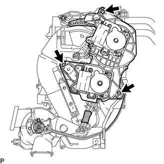
(c) Install the air conditioning radiator assembly to the blower assembly with cooler evaporator sub-assembly with the 6 screws. |
|
.png)
8. INSTALL COOLER EXPANSION VALVE
|
(a) Using a 4 mm hexagon wrench, install the cooler expansion valve with the 2 hexagon bolts. Torque: 3.5 N·m {36 kgf·cm, 31 in·lbf} |
|
.png)
9. INSTALL AIR CONDITIONING HARNESS ASSEMBLY
(a) Connect each connector.
.png)
(b) Engage each clamp to install the air conditioning harness assembly.
10. INSTALL NO. 2 AIR DUCT SUB-ASSEMBLY
|
(a) Engage the guide and 2 claws to install the No. 2 air duct sub-assembly as shown in the illustration. |
|
11. INSTALL NO. 3 AIR DUCT SUB-ASSEMBLY
|
(a) Engage the guide and 2 claws to install the No. 3 air duct sub-assembly as shown in the illustration. |
|
12. INSTALL NO. 2 FINISH PANEL MOUNTING BRACKET
|
(a) Install the No. 2 finish panel mounting bracket with the bolt as shown in the illustration. Torque: 9.8 N·m {100 kgf·cm, 87 in·lbf} |
|
13. INSTALL NO. 1 FINISH PANEL MOUNTING BRACKET
|
(a) Install the 2 No. 1 finish panel mounting brackets with the 2 bolts as shown in the illustration. Torque: 9.8 N·m {100 kgf·cm, 87 in·lbf} |
|
14. INSTALL TRANSPONDER KEY ECU ASSEMBLY (w/ Engine Immobiliser System)
 Disassembly
DISASSEMBLY
PROCEDURE
1. REMOVE TRANSPONDER KEY ECU ASSEMBLY (w/ Engine Immobiliser System)
2. REMOVE NO. 1 FINISH PANEL MOUNTING BRACKET
(a) Remove the 2 bolts and 2 No. 1 finish pa ...
 Installation
INSTALLATION
PROCEDURE
1. INSTALL AIR CONDITIONING UNIT ASSEMBLY
(a) Install the air conditioning unit assembly with the 3 nuts.
Torque:
9.8 N·m {100 kgf·cm, 87 in·lbf}
NOTICE:
Tighten th ...
Other materials about Toyota Venza:
Adjustment
ADJUSTMENT
CAUTION / NOTICE / HINT
CAUTION:
Before adjusting the door positions of vehicles equipped with side and curtain
shield airbags, be sure to disconnect the battery. After adjustment, check that
the SRS warning light is operating normally and ...
Removal
REMOVAL
PROCEDURE
1. PRECAUTION
(See page )
2. ALIGN FRONT WHEELS FACING STRAIGHT AHEAD
3. DISCONNECT CABLE FROM NEGATIVE BATTERY TERMINAL
CAUTION:
Wait at least 90 seconds after disconnecting the cable from the negative (-)
battery terminal to disab ...
Problem Symptoms Table
PROBLEM SYMPTOMS TABLE
HINT:
Use the table below to help determine the cause of problem symptoms.
If multiple suspected areas are listed, the potential causes of the symptoms
are listed in order of probability in the "Suspected Area" ...

0.1425