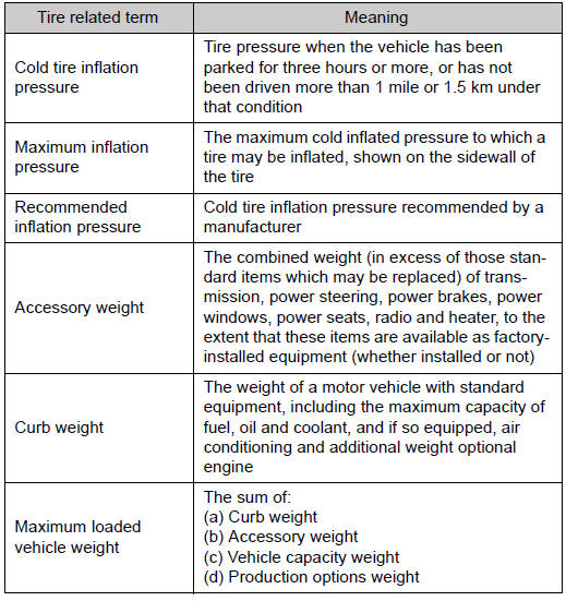
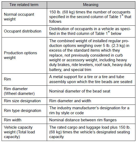
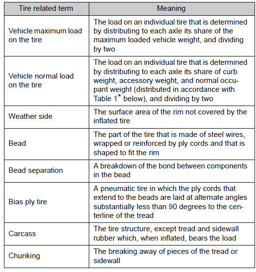
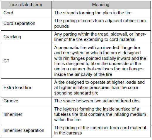
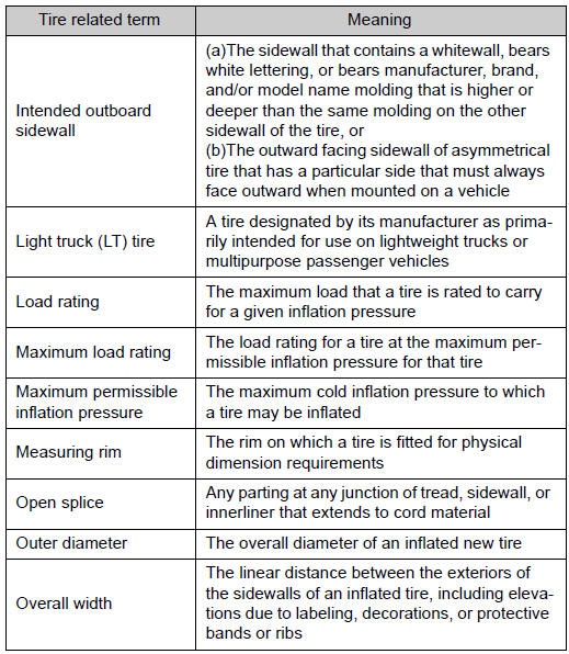
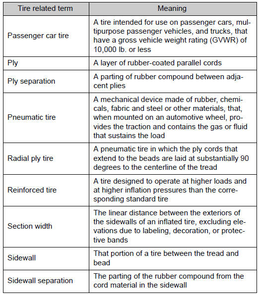
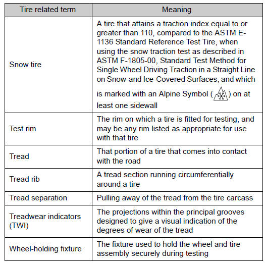
Toyota Venza: Glossary of tire terminology
 Uniform Tire Quality Grading
This information has been prepared in accordance with regulations issued by the
National Highway Traffic Safety Administration of the U.S. Department of Transportation.
It provides the purchasers a ...
 Customization
...
Other materials about Toyota Venza:
System Voltage (P0560)
DESCRIPTION
The battery supplies electricity to the ECM even when the ignition switch is
off. This power allows the ECM to store data such as DTC history, freeze frame data
and fuel trim values. If the battery voltage falls below a minimum level, the stor ...
Actuator Supply Voltage Circuit / Open (P0657)
MONITOR DESCRIPTION
The ECM monitors the output voltage to the throttle actuator. This self-check
ensures that the ECM is functioning properly. The output voltage is usually 0 V
when the ignition switch is turned off. If the output voltage is higher than ...
Power Source Mode does not Change to ON (IG and ACC)
DESCRIPTION
When the engine switch is pushed with the electrical key in the cabin, the power
management control ECU receives signals to change the power source mode.
HINT:
To allow use of the Techstream to inspect the push-button start function when
the ...

0.1121