Toyota Venza: Brake Override System
DESCRIPTION
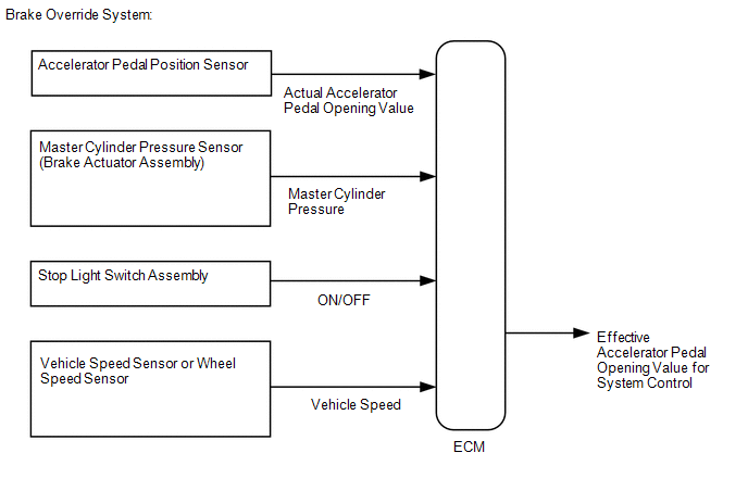
When the vehicle is being driven, depressing the accelerator pedal sensor assembly and brake pedal will activate the brake override system to restrict driving torque. The conditions for activating the brake override system as well as the items that are controlled are explained below.
 Activation Conditions:
- When the accelerator pedal and brake pedal are depressed.
NOTICE:
The vehicle may not enter the brake override system control due to the relation of the accelerator pedal angle and the vehicle's speed.
- When the vehicle speed is extremely low, the accelerator opening value
used when controlling the engine is reduced more than normal.
HINT:
During control, the Accelerator Position value in the Data List will be lower than normal.
- When the vehicle speed is not extremely low, the accelerator opening
value is forcibly lowered to a fixed value.
HINT:
During control, the Accelerator Position value in the Data List is forcibly reduced to a specified value regardless of the actual accelerator opening value (Accel Sens. No.1 Volt %).
- When the brake pedal or the accelerator pedal returns to some degree.
CAUTION / NOTICE / HINT
Inspection MethodExample:
Drive at 10 km/h (6.25 mph), depress the accelerator pedal by 1/2 to 3/4 and keep it in that position. Under these conditions, if the engine speed decreases to 1000 rpm when the brake pedal is depressed, then the brake override system has been activated.
CAUTION:
When carrying out the inspection, use a place where you are able to carry it out safely and also pay close attention to your surroundings.
Also, when driving make absolutely sure that all road traffic laws, such as speed limits, are observed.
HINT:
- Under normal conditions, the Accelerator Position value changes in response
to the Accel Sens. No.1 Volt % value. For more information on the numerical
values, refer to the Data List (See page
.gif) ).
). - If the Accelerator Position and Accel Sens. No.1 Volt % values in the Data List diverge and the Accelerator Position value in the Data List is fixed even though Accel Sens. No.1 Volt % is changing, check that this control is activated (use the Techstream data saving function to record data while driving the vehicle and then confirm it after driving is completed).
NOTICE:
The brake override system restricts driving torque if the brake pedal is depressed when driving with the accelerator pedal depressed. If a customer reports experiencing loss of torque after the accelerator and brake pedals have both been intentionally depressed, explain to the customer that this is not a malfunction, and that the customer should avoid depressing both the accelerator and brake pedals at the same time.
Example: While operating the accelerator pedal, the customer uses their left foot to operate the brake pedal.
PROCEDURE
|
1. |
CHECK DTC OUTPUT |
(a) Connect the Techstream to the DLC3.
(b) Turn the ignition switch to ON and turn the Techstream on.
(c) Enter the following menus: System Select / Health Check.
(d) Check for DTCs.
Result|
Result |
Proceed to |
|---|---|
|
DTC is not output |
A |
|
DTC is output |
B |
| B | .gif) |
GO TO DTC CHART |
|
.gif)
|
2. |
READ VALUE USING TECHSTREAM (MASTER CYLINDER SENSOR) |
(a) Connect the Techstream to the DLC3.
(b) Start the engine and turn the Techstream on.
(c) Enter the following menus: Chassis / ABS/VSC/TRAC / Data List / Master Cylinder Sensor.
(d) Read the value displayed on the Techstream.
OK:
|
Techstream Display |
Measurement Item/Range |
Normal Condition |
|---|---|---|
|
Master Cylinder Sensor |
Master cylinder pressure sensor reading/ Min.: 0.00 V, Max.: 5.00 V |
|
(e) Check that the brake fluid pressure value of the "Master Cylinder Sensor" observed on the Techstream changes when the brake pedal is depressed.
OK:
When the pedal is depressed, the voltage displayed on the Techstream increases.
| NG | |
REPLACE BRAKE ACTUATOR ASSEMBLY |
|
|
3. |
READ VALUE USING TECHSTREAM (STOP LIGHT SWITCH AND ST1) |
(a) Connect the Techstream to the DLC3.
(b) Turn the ignition switch to ON and turn the Techstream on.
(c) Enter the following menus: Powertrain / Engine / Data List / Stop Light Switch and ST1.
(d) Check the Data List indication when the brake pedal is depressed and released.
OK:
|
Techstream Display |
Condition |
Specified Condition |
|---|---|---|
|
Stop Light Switch |
Brake pedal released |
OFF |
|
Brake pedal depressed |
ON |
|
|
ST1 |
Brake pedal released |
OFF |
|
Brake pedal depressed |
ON |
| NG | |
INSPECT STOP LIGHT SWITCH ASSEMBLY |
|
|
4. |
INSPECT BRAKE PEDAL |
(a) Inspect and adjust the brake pedal (See page
).
HINT:
If the stop light switch turns on too late, the start of brake override system control may be delayed; if it turns ON too soon, brake override system control may begin too early, so conduct inspection of the brake pedal and stop light switch assembly.
| NG | |
REPAIR OR REPLACE BRAKE PEDAL |
|
|
5. |
READ VALUE USING TECHSTREAM (ACCELERATOR PEDAL POSITION SENSOR) |
(a) Connect the Techstream to the DLC3.
(b) Turn the ignition switch to ON and turn the Techstream on.
(c) Enter the following menus: Powertrain / Engine / Data List / Gas Throttle / Accel Sens. No.1 Volt % and Accel Sens. No.2 Volt %.
(d) Read the value displayed on the Techstream.
OK:
|
Techstream Display |
Condition |
Specified Condition |
|---|---|---|
|
Accel Sens. No.1 Volt % |
Accelerator Pedal Released → Depressed → Released |
Values smoothly change following accelerator pedal operation |
|
Accel Sens. No.2 Volt % |
HINT:
For numerical values of Accel Sens. No.1 Volt % and Accel Sens. No.2 Volt %,
refer to the Data List (See page ).
| NG | |
REPLACE ACCELERATOR PEDAL SENSOR ASSEMBLY |
|
|
6. |
READ VALUE USING TECHSTREAM (VEHICLE SPEED) |
(a) Connect the Techstream to the DLC3.
(b) Turn the ignition switch to ON and turn the Techstream on.
(c) Start the engine.
(d) Enter the following menus: Powertrain / Engine / Data List / Vehicle Speed.
(e) Read the value displayed on the Techstream.
Standard:
|
Techstream Display |
Condition |
Specified Condition |
|---|---|---|
|
Vehicle Speed |
Vehicle stopped, engine running |
0 km/h (0 mph) |
|
Vehicle running at constant speed between 16.1 to 64.4 km/h (10 to 40 mph) |
No large fluctuations when driving at a constant speed |
CAUTION:
When performing a drive test, obey all speed limits and traffic laws.
HINT:
Data can be captured relatively easily by using the snapshot function in the Data List. Confirm the data after performing the drive test.
| NG | |
GO TO METER / GAUGE SYSTEM (SPEED SIGNAL CIRCUIT) |
|
|
7. |
READ VALUE USING TECHSTREAM (FR, FL, RR, RL WHEEL SPEED) |
(a) Connect the Techstream to the DLC3.
(b) Turn the ignition switch to ON and turn the Techstream on.
(c) Start the engine.
(d) Enter the following menus: Chassis / ABS/VSC/TRAC / Data List / FR Wheel Speed, FL Wheel Speed, RR Wheel Speed and RL Wheel Speed.
(e) Read the value displayed on the Techstream.
Standard:
|
Techstream Display |
Condition |
Specified Condition |
|---|---|---|
|
FR Wheel Speed FL Wheel Speed RR Wheel Speed RL Wheel Speed |
Vehicle stopped, engine running |
0 km/h (0 mph) |
|
Vehicle running at constant speed between 16.1 to 64.4 km/h (10 to 40 mph) |
No large fluctuations when driving at a constant speed |
CAUTION:
When performing a drive test, obey all speed limits and traffic laws.
HINT:
Data can be captured relatively easily by using the snapshot function in the Data List. Confirm the data after performing the drive test.
| OK | |
END |
| NG | |
INSPECT FRONT OR REAR SPEED SENSOR |
 Starter Signal Circuit
DESCRIPTION
1. w/o Smart Key System
While the engine is being cranked, current flows from terminal ST1 of the ignition
switch assembly to the park/neutral position switch assembly and also flows t ...
 MIL Circuit
DESCRIPTION
The MIL (Malfunction Indicator Lamp) is used to indicate vehicle malfunctions
detected by the ECM. By turning the ignition switch to ON, power is supplied to
the MIL circuit, and the ...
Other materials about Toyota Venza:
Main Body ECU Vehicle Information Reading/Writing Process Malfunction (B15F6)
DESCRIPTION
This DTC is stored when items controlled by the main body ECU (multiplex network
body ECU) cannot be customized via the audio and visual system vehicle customization
screen.
HINT:
The main body ECU (multiplex network body ECU) controls t ...
Assist Map Number Mismatch (C1582)
DESCRIPTION
When an incorrect ECM or brake actuator assembly (skid control ECU) is installed
after the assist map has been recorded in the power steering ECU, then DTC C1582
is stored because the data does not match the vehicle specifications.
...
Disassembly
DISASSEMBLY
PROCEDURE
1. REMOVE ULTRASONIC SENSOR CLIP (w/ Intuitive Parking Assist System)
2. REMOVE NO. 1 ULTRASONIC SENSOR (w/ Intuitive Parking Assist System)
3. REMOVE NO. 1 ULTRASONIC SENSOR RETAINER (w/ Intuitive Parking Assist System)
4. ...

0.1744