Toyota Venza: Checking and replacing fuses
If any of the electrical components do not operate, a fuse may have blown. If this happens, check and replace the fuses as necessary.
 Vehicles with smart key system:
Turn the “ENGINE START STOP” switch off.
Vehicles without smart key system:
Turn the engine switch to the “LOCK” position.
 Open the fuse box cover.
► Engine compartment
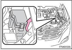
Push the tab in and lift the lid off.
► Driver’s side instrument panel
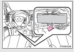
Remove the lid.
 After a system failure, see “Fuse
layout and amperage ratings” for details about which fuse to check.
Remove the fuse with the pullout tool.
 Check if the fuse has blown.
►Type A
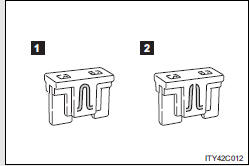
1. Normal fuse
2. Blown fuse
Replace it with one of an appropriate amperage rating.
The amperage rating can be found on the fuse box lid.
►Type B
1. Normal fuse
2. Blown fuse
Contact your Toyota dealer.
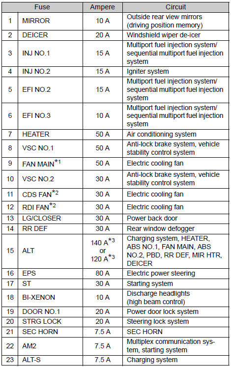
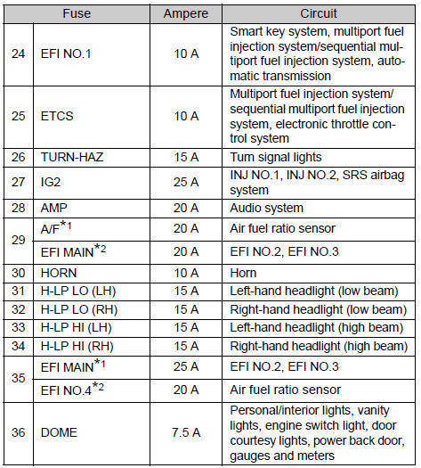
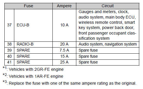
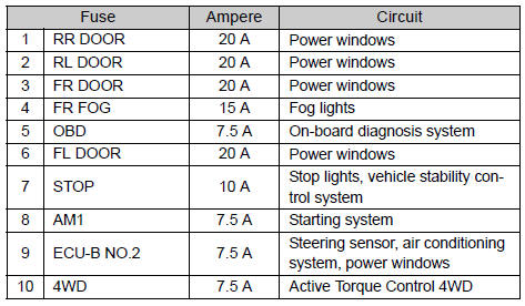
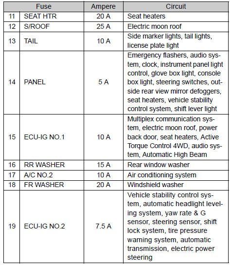
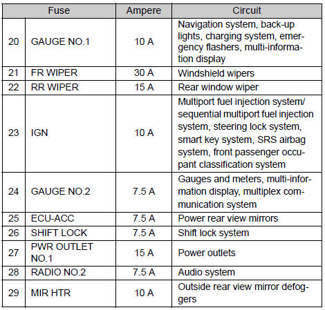
Fuse layout and amperage ratings
- Engine compartment
►Fuse block
►Back of the cover
- Driver’s side instrument panel
- After a fuse is replaced
• If the lights do not turn on even after the fuse has been replaced, a bulb may
need replacement.
• If the replaced fuse blows again, have the vehicle inspected by your Toyota dealer.
- If there is an overload in the circuits
The fuses are designed to blow, protecting the wiring harness from damage.
CAUTION
- To prevent system breakdowns and vehicle fire
Observe the following precautions.
Failing to do so may cause damage to the vehicle, and possibly a fire or injury.
• Never use a fuse of a higher amperage rating than indicated, or use any other object in place of a fuse.
• Always use a genuine Toyota fuse or equivalent.
Never replace a fuse with a wire, even as a temporary fix.
• Do not modify fuses or the fuse box.
NOTICE
- Before replacing fuses
Have the cause of electrical overload determined and repaired by your Toyota dealer.
 Key battery
Replace the battery with a new one if it is discharged.
- You will need the following items:
• Flathead screwdriver (To prevent damage to the key, cover the tip of the screwdriver
with rag ...
 Light bulbs
You may replace the following bulbs yourself. The difficulty level of replacement
varies depending on the bulb. If necessary bulb replacement seems difficult to perform,
contact your Toyota dealer ...
Other materials about Toyota Venza:
Operation Check
OPERATION CHECK
1. AUTOMATIC LIGHT CONTROL SYSTEM OPERATION CHECK
(a) Turn the ignition switch to ON.
(b) Turn the light control switch to the AUTO position.
(c) Cover the automatic light control sensor.
(d) Check that the taillights and low beam headligh ...
Steering Angle Sensor Circuit Malfunction (C1231/31)
DESCRIPTION
The steering angle sensor signal is sent to the skid control ECU via the CAN
communication system. When there is a malfunction in the CAN communication system,
it will be detected by the steering angle sensor zero point malfunction diagnostic ...
Front Stabilizer Bar(when Not Using The Engine Support Bridge For Awd)
Components
COMPONENTS
ILLUSTRATION
Inspection
INSPECTION
PROCEDURE
1. INSPECT FRONT STABILIZER LINK ASSEMBLY
(a) Inspect the turning torque of the ball joint.
(1) Secure the front stabilizer link assembly in a vise using aluminum
...

0.1487