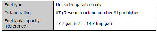
Toyota Venza: Fuel
 Engine
...
 Lubrication system
- Engine oil selection
“Toyota Genuine Motor Oil” is used in your Toyota vehicle. Use Toyota approved
“Toyota Genuine Motor Oil” or equivalent to satisfy the following grade and vis ...
Other materials about Toyota Venza:
Removal
REMOVAL
PROCEDURE
1. REMOVE NO. 1 FLOOR UNDER COVER
(a) Disengage the 4 nuts and clip, and remove the No. 1 floor under cover.
Text in Illustration
Nut (attached to under cover)
HINT:
Rotate the clip to disengage it. The 4 ...
Components
COMPONENTS
ILLUSTRATION
ILLUSTRATION
ILLUSTRATION
ILLUSTRATION
ILLUSTRATION
...
Removal
REMOVAL
PROCEDURE
1. REMOVE REAR WHEELS
2. REMOVE CENTER EXHAUST PIPE ASSEMBLY
(a) Remove the center exhaust pipe assembly.
HINT:
Refer to the instructions for Removal of the exhaust pipe (See page
for 2GR-FE,
for 1AR-FE).
3. REMOVE LOWER NO. 1 EXH ...
© 2016-2026 Copyright www.tovenza.com

0.1146
0.1146