Toyota Venza: Front Door Speaker
Components
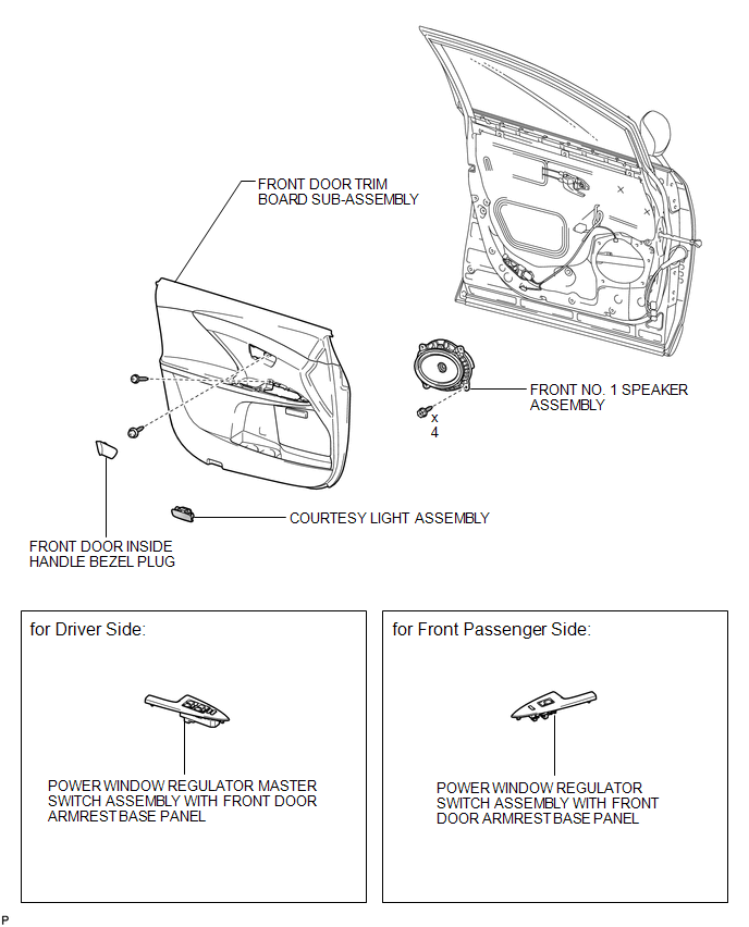
COMPONENTS
ILLUSTRATION
Removal
REMOVAL
PROCEDURE
1. DISCONNECT CABLE FROM NEGATIVE BATTERY TERMINAL
CAUTION:
Wait at least 90 seconds after disconnecting the cable from the negative (-)
battery terminal to disable the SRS system (See page
.gif) ).
).
NOTICE:
When disconnecting the cable, some systems need to be initialized after the cable
is reconnected (See page ).
2. REMOVE FRONT DOOR INSIDE HANDLE BEZEL PLUG
3. REMOVE POWER WINDOW REGULATOR MASTER SWITCH ASSEMBLY WITH FRONT DOOR ARMREST BASE PANEL (for Driver Side)
4. REMOVE POWER WINDOW REGULATOR SWITCH ASSEMBLY WITH FRONT DOOR ARMREST BASE PANEL (for Front Passenger Side)
5. REMOVE COURTESY LIGHT ASSEMBLY
6. REMOVE FRONT DOOR TRIM BOARD SUB-ASSEMBLY
7. REMOVE FRONT NO. 1 SPEAKER ASSEMBLY
|
(a) Disconnect the connector. |
|
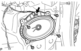
(b) Remove the 4 bolts and the front No. 1 speaker assembly.
Inspection
INSPECTION
PROCEDURE
1. INSPECT FRONT NO. 1 SPEAKER ASSEMBLY
(a) With the speaker installed, check that there is no looseness or other abnormalities.
(b) Check that there is no foreign matter in the speaker, no tears on the speaker cone or other abnormalities.
|
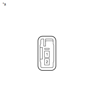
(c) Measure the resistance of the speaker. Standard Resistance: for 6 Speakers:
If the result is not as specified, replace the speaker. Text in Illustration
|
|
Installation
INSTALLATION
PROCEDURE
1. INSTALL FRONT NO. 1 SPEAKER ASSEMBLY
|
(a) Install the front No. 1 speaker assembly with the 4 bolts. |
|
.png)
(b) Connect the connector.
2. INSTALL FRONT DOOR TRIM BOARD SUB-ASSEMBLY
.gif)
3. INSTALL COURTESY LIGHT ASSEMBLY
4. INSTALL POWER WINDOW REGULATOR MASTER SWITCH ASSEMBLY WITH FRONT DOOR ARMREST BASE PANEL (for Driver Side)
5. INSTALL POWER WINDOW REGULATOR SWITCH ASSEMBLY WITH FRONT DOOR ARMREST BASE PANEL (for Front Passenger Side)
6. INSTALL FRONT DOOR INSIDE HANDLE BEZEL PLUG
7. CONNECT CABLE TO NEGATIVE BATTERY TERMINAL
NOTICE:
When disconnecting the cable, some systems need to be initialized after the cable
is reconnected (See page ).
 Radio Receiver Power Source Circuit
DESCRIPTION
This is the power source circuit to operate the radio and display receiver assembly.
WIRING DIAGRAM
CAUTION / NOTICE / HINT
NOTICE:
Inspect the fuses for circuits related to this sy ...

Other materials about Toyota Venza:
System Description
SYSTEM DESCRIPTION
1. GENERAL
(a) Deceleration sensors used for the airbag system are installed on various
parts on the vehicle and calculate the deceleration rate of each part during a collision.
(b) Depending on the situation, the center airbag sensor a ...
ECM / PCM Processor (P0606)
MONITOR DESCRIPTION
The ECM continuously monitors its main and sub CPUs. This self-check ensures
that the ECM is functioning properly. If outputs from the CPUs are different and
deviate from the standard, the ECM illuminates the MIL and stores the DTC imm ...
Installation
INSTALLATION
PROCEDURE
1. INSTALL HOOD LOCK CONTROL CABLE ASSEMBLY
(a) Pass the hood lock control cable assembly into the engine compartment.
(b) Pass the cable through the upper radiator support.
(c) Engage the each clamp shown in the illustration.
2. I ...

0.1642