Toyota Venza: Removal
REMOVAL
PROCEDURE
1. REMOVE NO. 1 ENGINE COVER SUB-ASSEMBLY
.gif)
2. REMOVE CAMSHAFT TIMING OIL CONTROL VALVE ASSEMBLY (for Exhaust Side)
|
(a) Disconnect the oil control valve connector. |
|
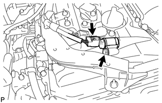
(b) Remove the bolt and oil control valve.
|
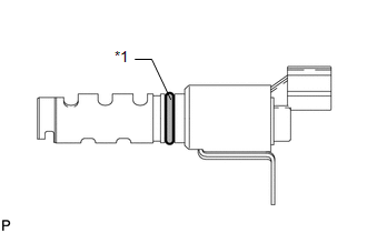
(c) Remove the O-ring from the oil control valve. Text in Illustration
|
|
3. REMOVE CAMSHAFT TIMING OIL CONTROL VALVE ASSEMBLY (for Intake Side)
|
(a) Disconnect the oil control valve connector. |
|
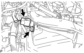
(b) Remove the bolt and oil control valve.
|
(c) Remove the O-ring from the oil control valve. Text in Illustration
|
|
 On-vehicle Inspection
ON-VEHICLE INSPECTION
PROCEDURE
1. INSPECT CAMSHAFT TIMING OIL CONTROL VALVE ASSEMBLY
(a) Connect the Techstream to the DLC3.
(b) Start the engine and turn the Techstream on.
(c) Inspect the oil ...
 Inspection
INSPECTION
CAUTION / NOTICE / HINT
HINT:
Use the same procedure for the intake side and exhaust side.
PROCEDURE
1. INSPECT CAMSHAFT TIMING OIL CONTROL VALVE ASSEMBLY
(a) Measure the r ...
Other materials about Toyota Venza:
Inspection
INSPECTION
PROCEDURE
1. INSPECT EVAPORATOR TEMPERATURE SENSOR
(a) Measure the resistance according to the value(s) in the table below.
Standard Resistance:
Tester Connection
Condition
Specified Condition
...
Seat Heater Switch
Components
COMPONENTS
ILLUSTRATION
Removal
REMOVAL
PROCEDURE
1. REMOVE UPPER CONSOLE PANEL SUB-ASSEMBLY
2. REMOVE SEAT HEATER SWITCH
(a) Disengage the 2 claws and remove the seat heater switch as shown
in the illustration.
...
Reassembly
REASSEMBLY
CAUTION / NOTICE / HINT
NOTICE:
When using a vise, do not overtighten it.
PROCEDURE
1. INSTALL STEERING LOCK ACTUATOR ASSEMBLY (w/ Smart Key System)
(a) Secure the steering column assembly in a vise.
(b) Temporarily install the ste ...

0.1753