Toyota Venza: Evaporative Emission System Leak Detection Reference Orifice Low Flow (P043E,P043F,P2401,P2402,P2419)
DTC SUMMARY
|
DTC No. |
Monitoring Item |
Malfunction Detection Condition |
Trouble Area |
Detection Timing |
Detection Logic |
|---|---|---|---|---|---|
|
P043E |
Reference orifice clogged |
P043E, P043F, P2401, P2402 and P2419 stored when one of following conditions met during key-off EVAP monitor:
|
|
While ignition switch off |
2 trip |
|
P043F |
Reference orifice high-flow |
||||
|
P2401 |
Leak detection pump stuck OFF |
||||
|
P2402 |
Leak detection pump stuck ON |
||||
|
P2419 |
Vent valve stuck closed |
HINT:
The reference orifice is located inside the canister pump module.
DESCRIPTION
The description can be found in EVAP (Evaporative Emission) System (See page
.gif) ).
).
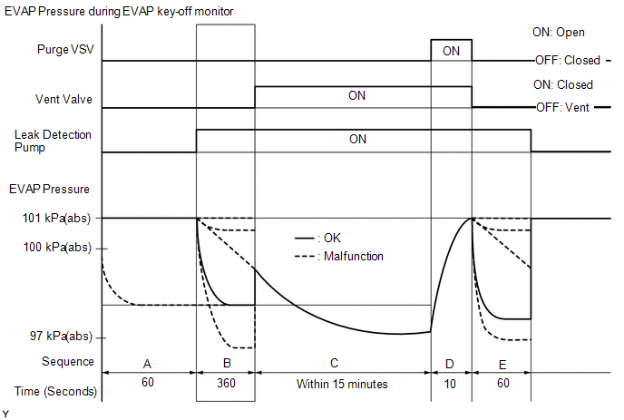
MONITOR DESCRIPTION
5 hours* after the ignition switch is turned off, the leak detection pump creates negative pressure (vacuum) in the EVAP system. The ECM monitors for leaks and actuator malfunctions based on the EVAP pressure.
HINT:
*: If the engine coolant temperature is not below 35°C (95°F) 5 hours after the ignition switch is turned off, the monitor check starts 2 hours later. If it is still not below 35°C (95°F) 7 hours after the ignition switch is turned off, the monitor check starts 2.5 hours later.
|
Sequence |
Operation |
Description |
Duration |
|---|---|---|---|
|
- |
ECM activation |
Activated by soak timer, 5, 7 or 9.5 hours after ignition switch turned off. |
- |
|
A |
Atmospheric pressure measurement |
Vent valve is turned off (vent) and EVAP system pressure is measured by ECM in order to register atmospheric pressure. If pressure in EVAP system is not between 70 kPa(abs) and 110 kPa(abs) [525 mmHg(abs) and 825 mmHg(abs)], ECM cancels EVAP system monitor. |
60 seconds |
|
B |
First reference pressure measurement |
In order to determine reference pressure, leak detection pump creates negative pressure (vacuum) through reference orifice and then ECM checks if leak detection pump and vent valve operate normally. |
360 seconds |
|
C |
EVAP system pressure measurement |
Vent valve is turned on (closed) to shut EVAP system. Negative pressure (vacuum) is created in EVAP system, and EVAP system pressure is then measured. Write down measured value as it will be used in leak check If EVAP pressure does not stabilize within 15 minutes, ECM cancels EVAP system monitor. |
15 minutes* |
|
D |
Purge VSV monitor |
Purge VSV is opened and then EVAP system pressure is measured by ECM. Large increase indicates normal. |
10 seconds |
|
E |
Second reference pressure measurement |
After second reference pressure measurement, leak check is performed by comparing first and second reference pressure measurements. If stabilized system pressure is higher than second reference pressure, ECM determines that EVAP system is leaking. |
60 seconds |
|
- |
Final check |
Atmospheric pressure is measured and then monitoring result is recorded by ECM. |
- |
*: If only a small amount of fuel is in the fuel tank, it takes longer for the EVAP pressure to stabilize.
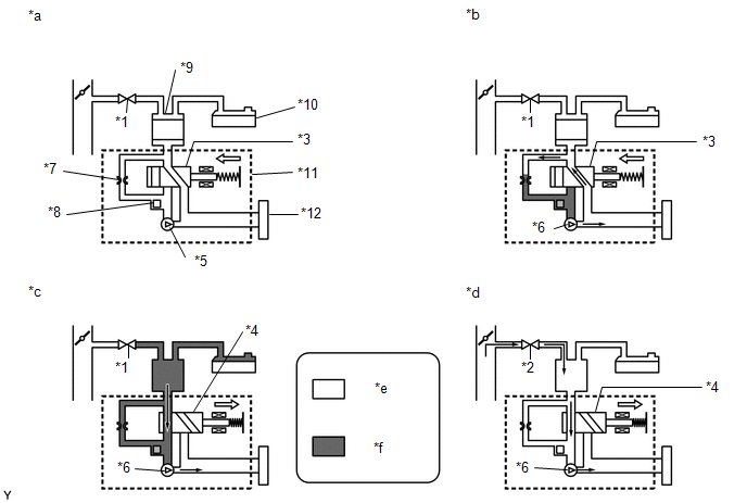 Text in Illustration
|
*1 |
Purge VSV: Off (Closed) |
*2 |
Purge VSV: On (Open) |
|
*3 |
Vent Valve: Off (Vent) |
*4 |
Vent Valve: On (Closed) |
|
*5 |
Leak Detection Pump: Off |
*6 |
Leak Detection Pump: On |
|
*7 |
Reference Orifice (0.02 inch) |
*8 |
Canister Pressure Sensor |
|
*9 |
Canister |
*10 |
Fuel Tank |
|
*11 |
Canister Pump Module |
*12 |
Canister Filter |
|
*a |
Operation A: Atmospheric Pressure Measurement |
*b |
Operation B, E: Reference Pressure Measurement |
|
*c |
Operation C: EVAP System Pressure Measurement |
*d |
Operation D: Purge VSV Monitor |
|
*e |
Atmospheric Pressure |
*f |
Negative Pressure |
The leak detection pump creates negative pressure through the reference orifice (in operation B and E). When the system is normal, the EVAP pressure is between 97 to 100 kPa(abs) [726 to 750 mmHg(abs)]* and saturated within a minute. If not, the ECM interprets this as a malfunction. The ECM illuminates the MIL and stores a DTC if this malfunction is detected in consecutive drive cycles.
*: Typical value.
MONITOR STRATEGY
|
Required Sensors/Components |
Canister pump module |
|
Frequency of Operation |
Once per driving cycle |
|
Duration |
Within 7 minutes |
|
MIL Operation |
2 driving cycles |
|
Sequence of Operation |
None |
TYPICAL ENABLING CONDITIONS
|
Monitor runs whenever the following DTCs are not stored |
None |
|
Atmospheric pressure |
70 kPa(abs) [525 mmHg(abs)] or higher, and less than 110 kPa(abs) [825 mmHg(abs)] |
|
Battery voltage |
10.5 V or higher |
|
Vehicle speed |
Less than 4 km/h (2.5 mph) |
|
Ignition switch |
Off |
|
Time after key-off |
5, 7 or 9.5 hours |
|
Canister pressure sensor malfunction |
Not detected |
|
Purge VSV |
Not operated by scan tool |
|
Vent valve |
Not operated by scan tool |
|
Leak detection pump |
Not operated by scan tool |
|
Both of following conditions met before key-off |
Conditions 1 and 2 |
|
1. Duration that vehicle is driven |
5 minutes or more |
|
2. EVAP purge operation |
Performed |
|
Engine coolant temperature |
4.4°C (40°F) or higher, and less than 35°C (95°F) |
|
Intake air temperature |
4.4°C (40°F) or higher, and less than 35°C (95°F) |
TYPICAL MALFUNCTION THRESHOLDS
"Saturated" indicates that the EVAP pressure change is below 0.286 kPa(gauge) [2.145 mmHg(gauge)] in 60 seconds.
|
One of following conditions met |
- |
|
EVAP pressure just after reference pressure measurement started |
Higher than -0.25 kPa(gauge) [-1.875 mmHg(gauge)] |
|
Reference pressure |
Below -4.85 kPa(gauge) [-36.38 mmHg(gauge)] |
|
Reference pressure |
-1.057 kPa(gauge) [-7.929 mmHg(gauge)] or higher |
|
Reference pressure |
Not saturated within 360 seconds |
|
Reference pressure difference between first and second |
0.9 kPa(gauge) [6.751 mmHg(gauge)] or higher |
MONITOR RESULT
Refer to Checking Monitor Status (See page
).
CONFIRMATION DRIVING PATTERN
NOTICE:
- The Evaporative System Check (Automatic Mode) consists of 6 steps performed automatically by the Techstream. It takes a maximum of approximately 24 minutes.
- Do not perform the Evaporative System Check when the fuel tank is more than 90% full because the cut-off valve may be closed, making the fuel tank leak check unavailable.
- Do not run the engine during this operation.
- When the temperature of the fuel is 35°C (95°F) or higher, a large amount of vapor forms and any check results become inaccurate. When performing the Evaporative System Check, keep the fuel temperature below 35°C (95°F).
- Connect the Techstream to the DLC3.
- Turn the ignition switch to ON and turn the Techstream on.
- Clear the DTCs (even if no DTCs are stored, perform the clear DTC procedure)
(See page ).
- Turn the ignition switch off and wait for at least 30 seconds.
- Turn the ignition switch to ON and turn the Techstream on.
- Enter the following menus: Powertrain / Engine / Utility / Evaporative System Check / Automatic Mode.
- After the Evaporative System Check is completed, check for All Readiness by entering the following menus: Powertrain / Engine / Utility / All Readiness.
- Input the DTC: P043E, P043F, P2401, P2402 or P2419.
- Check the DTC judgment result.
Techstream Display
Description
NORMAL
- DTC judgment completed
- System normal
ABNORMAL
- DTC judgment completed
- System abnormal
INCOMPLETE
- DTC judgment not completed
- Perform driving pattern after confirming DTC enabling conditions
N/A
- Unable to perform DTC judgment
- Number of DTCs which do not fulfill DTC preconditions has reached ECU memory limit
HINT:
- If the judgment result shows NORMAL, the system is normal.
- If the judgment result shows ABNORMAL, the system has a malfunction.
- If the test result is INCOMPLETE or N/A and no pending DTC is output,
perform a universal trip and check for permanent DTCs (See page
).
HINT:
- If a permanent DTC is output, the system is malfunctioning.
- If no permanent DTC is output, the system is normal.
PROCEDURE
|
1. |
REFER TO THE EVAP SYSTEM |
Refer to EVAP System (See page ).
| NEXT | .gif) |
END |
 Catalyst System Efficiency Below Threshold (Bank 1) (P0420)
MONITOR DESCRIPTION
The ECM uses sensors mounted in front of and behind the Three-Way Catalytic Converter
(TWC) to monitor its efficiency.
The first sensor, the air fuel ratio sensor, sends pre-ca ...
 Evaporative Emission Control System Incorrect Purge Flow (P0441)
DTC SUMMARY
DTC No.
Monitoring Item
Malfunction Detection Condition
Trouble Area
Detection Timing
Detection Logic
P0 ...
Other materials about Toyota Venza:
Data List / Active Test
DATA LIST / ACTIVE TEST
1. DATA LIST
NOTICE:
In the table below, the values listed under "Normal Condition" are reference
values. Do not depend solely on these reference values when deciding whether a part
is faulty or not.
HINT:
Using the T ...
Inspection
INSPECTION
PROCEDURE
1. INSPECT FRONT DIFFERENTIAL CASE
(a) Using SST, rotate the front differential side gear as shown in the
illustration.
SST: 09528-52010
09528-05030
Standard:
The front differential side gear does not lock wh ...
Problem Symptoms Table
PROBLEM SYMPTOMS TABLE
HINT:
Use the table below to help determine the cause of problem symptoms. If multiple
suspected areas are listed, the potential causes of the symptoms are listed in order
of probability in the "Suspected Area" column of ...

0.1374