Toyota Venza: ECM Communication Stop Mode
DESCRIPTION
|
Detection Item |
Symptom |
Trouble Area |
|---|---|---|
|
ECM Communication Stop Mode |
|
|
WIRING DIAGRAM
CAUTION / NOTICE / HINT
NOTICE:
- Turn the ignition switch off before measuring the resistances between CAN bus main wires and between CAN bus branch wires.
- Turn the ignition switch off before inspecting CAN bus wires for a ground short.
- After the ignition switch is turned off, check that the key reminder warning system and light reminder warning system are not operating.
- Before measuring the resistance, leave the vehicle as is for at least 1 minute and do not operate the ignition switch, any other switches or the doors. If any doors need to be opened in order to check connectors, open the doors and leave them open.
HINT:
- Operating the ignition switch, any other switches or a door triggers related ECU and sensor communication on the CAN. This communication will cause the resistance value to change.
- Even after DTCs are cleared, if a DTC is stored again after driving the vehicle for a while, the malfunction may be occurring due to vibration of the vehicle. In such a case, wiggling the ECUs or wire harness while performing the inspection below may help determine the cause of the malfunction.
PROCEDURE
|
1. |
CHECK CAN BUS WIRE FOR DISCONNECTION (ECM MAIN WIRE) |
(a) Turn the ignition switch off.
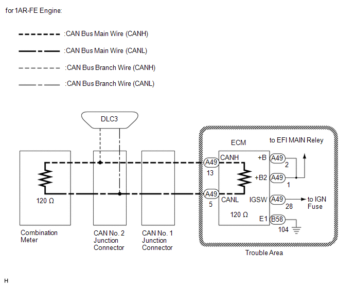
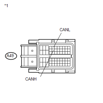
(b) for 1AR-FE engine:
|
(1) Disconnect the connector of the ECM. Text in Illustration
|
|
(2) Measure the resistance according to the value(s) in the table below.
Standard Resistance:
|
Tester Connection |
Switch Condition |
Specified Condition |
|---|---|---|
|
A49-13 (CANH) - A49-5 (CANL) |
Ignition switch off |
108 to 132 Ω |
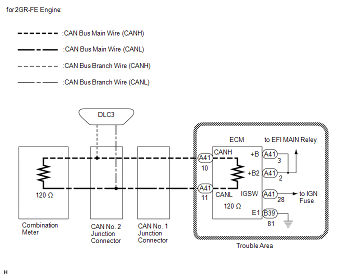
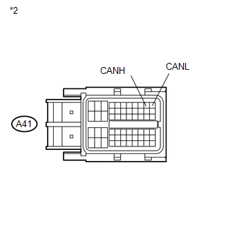
(c) for 2GR-FE engine:
|
(1) Disconnect the connector of the ECM. Text in Illustration
|
|
(2) Measure the resistance according to the value(s) in the table below.
Standard Resistance:
|
Tester Connection |
Switch Condition |
Specified Condition |
|---|---|---|
|
A41-10 (CANH) - A41-11 (CANL) |
Ignition switch off |
108 to 132 Ω |
| NG | .gif) |
REPAIR OR REPLACE CAN BUS MAIN WIRE OR CONNECTOR (ECM MAIN WIRE) |
|
.gif)
|
2. |
CHECK HARNESS AND CONNECTOR (POWER SOURCE TERMINAL) |
(a) Check for ECM Power Source Circuit (1AR-FE: See page
.gif) , 2GR-FE: See page
).
, 2GR-FE: See page
).
|
Result |
Proceed to |
|---|---|
|
OK (for 1AR-FE engine) |
A |
|
OK (for 2GR-FE engine) |
B |
|
NG |
C |
| A | |
REPLACE ECM |
| B | |
REPLACE ECM |
| C | |
REPAIR OR REPLACE HARNESS OR CONNECTOR (POWER SOURCE CIRCUIT) |
 Yaw Rate Sensor Communication Stop Mode
DESCRIPTION
Detection Item
Symptom
Trouble Area
Yaw Rate Sensor Communication Stop Mode
"Yaw Rate/Decelerate Sensor" ...
 Main Body ECU Communication Stop Mode
DESCRIPTION
Detection Item
Symptom
Trouble Area
Main Body ECU Communication Stop Mode
"Main Body" is not displayed on ...
Other materials about Toyota Venza:
Power Mirror Control System(w/o Memory)
Parts Location
PARTS LOCATION
ILLUSTRATION
Problem Symptoms Table
PROBLEM SYMPTOMS TABLE
HINT:
Use the table below to help determine the cause of problem symptoms. If multiple
suspected areas are listed, the potential causes of the symptoms are l ...
Engine
General Maintenance
GENERAL MAINTENANCE
CAUTION / NOTICE / HINT
HINT:
Perform these procedures after the engine has cooled down.
PROCEDURE
1. INSPECT DRIVE BELT
Engine Type
See Procedure
2GR-FE
See pag ...
On-vehicle Inspection
ON-VEHICLE INSPECTION
CAUTION / NOTICE / HINT
CAUTION:
Be sure to follow the correct removal and installation procedures of the door
side airbag sensor.
PROCEDURE
1. INSPECT DOOR SIDE AIRBAG SENSOR (VEHICLE NOT INVOLVED IN COLLISION)
(a) Perform a diag ...

0.1174