Toyota Venza: Lost Communication with TCM (U0101)
DESCRIPTION
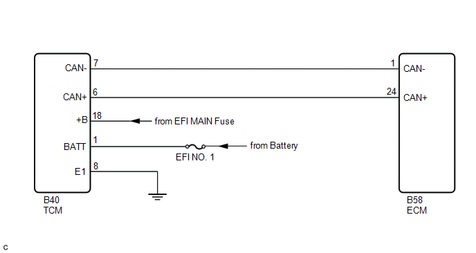
The Transmission Control Module (TCM) and ECM perform 2-way communication with each other via the Controller Area Network (CAN). The TCM sends signals to the ECM concerning required engine speed, required engine torque, warning indicators in the combination meter, DTCs and other data. The ECM sends signals to the TCM concerning engine speed, opening angle of the throttle valve, temperature of intake air, temperature of engine coolant, engine torque and other data. If the TCM cannot communicate with the ECM, the TCM will conclude that there is a malfunction in the CAN system, illuminate the MIL and set a DTC.
|
DTC No. |
DTC Detection Condition |
Trouble Area |
|---|---|---|
|
U0101 |
|
|
MONITOR STRATEGY
|
Related DTCs |
U0101: Lost Communication with TCM |
|
Required Sensors/Components (Main) |
ECM |
|
Required Sensors/Components (Related) |
- |
|
Frequency of Operation |
Continuous |
|
Duration |
1.25 seconds |
|
MIL Operation |
Immediate |
|
Sequence of Operation |
None |
TYPICAL ENABLING CONDITIONS
|
Monitor runs whenever following DTCs are not present |
None |
|
All of the following conditions are met |
- |
|
Battery voltage |
10.5 V or more (More than 1 second) |
|
Ignition switch |
ON |
|
Starter |
Off |
TYPICAL MALFUNCTION THRESHOLDS
|
Communication signal |
Lost communication with TCM |
CONFIRMATION DRIVING PATTERN
- Connect the Techstream to the DLC3.
- Turn the ignition switch to ON and turn the Techstream on.
- Clear the DTCs (even if no DTCs are stored, perform the Clear DTC procedure)
(See page
.gif) ).
). - Turn the ignition switch off and wait for at least 30 seconds.
- Turn the ignition switch to ON and turn the Techstream on.
- Wait 5 seconds or more.
- Enter the following menus: Powertrain / Engine / Trouble Codes.
- Read the Pending DTCs.
HINT:
- If a pending DTC is output, the system is malfunctioning.
- If a pending DTC is not output, perform the following procedure.
- Enter the following menus: Powertrain / Engine / Utility / All Readiness.
- Input the DTC: U0101.
- Check the DTC judgment result.
Techstream Display
Description
NORMAL
- DTC judgment completed
- System normal
ABNORMAL
- DTC judgment completed
- System abnormal
INCOMPLETE
- DTC judgment not completed
- Perform driving pattern after confirming DTC enabling conditions
N/A
- Unable to perform DTC judgment
- Number of DTCs which do not fulfill DTC preconditions has reached ECU's memory limit
HINT:
- If the judgment result shows NORMAL, the system is normal.
- If the judgment result shows ABNORMAL, the system has a malfunction.
- If the test result is INCOMPLETE or N/A and no pending DTC is output,
perform a universal trip and check for permanent DTCs (See page
).
HINT:
- If a permanent DTC is output, the system is malfunctioning.
- If no permanent DTC is output, the system is normal.
WIRING DIAGRAM
CAUTION / NOTICE / HINT
NOTICE:
Inspect the fuses for circuits related to this system before performing the following inspection procedure.
HINT:
Read freeze frame data using the Techstream. The ECM records vehicle and driving condition information as freeze frame data the moment a DTC is stored. When troubleshooting, freeze frame data can help determine if the vehicle was moving or stationary, if the engine was warmed up or not, if the air fuel ratio was lean or rich, and other data from the time the malfunction occurred.
PROCEDURE
|
1. |
CHECK OTHER DTC OUTPUT (IN ADDITION TO DTC U0101) |
(a) Connect the Techstream to the DLC3.
(b) Turn the ignition switch to ON.
(c) Turn the Techstream on.
(d) Enter the following menus: System Select / Health Check.
(e) Read the DTCs.
|
Result |
Proceed to |
|---|---|
|
DTC U0101 is output |
A |
|
DTC U0101 and other DTCs are output |
B |
HINT:
If any DTCs other than U0101 are output, troubleshoot those DTCs first.
| B | .gif) |
GO TO DTC CHART |
|
.gif)
|
2. |
INSPECT ECU POWER SOURCE CIRCUIT (TCM POWER SOURCE) |
|
(a) Disconnect the TCM connector. |
|
(b) Turn the Ignition switch to ON.
(c) Measure the voltage according to the value(s) in the table below.
Standard Voltage:
|
Tester Connection |
Condition |
Specified Condition |
|---|---|---|
|
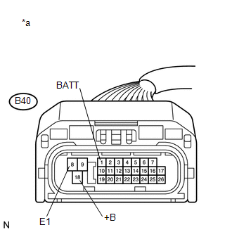
B40-1 (BATT) - B40-8 (E1) |
Always |
11 to 14 V |
|
B40-18 (+B) - B40-8 (E1) |
Ignition switch ON |
11 to 14 V |
|
*a |
Front view of wire harness connector (to TCM) |
|
Result |
Proceed to |
|---|---|
|
OK |
A |
|
NG (for U760E) |
B |
|
NG (for U760F) |
C |
| B | |
GO TO TCM POWER SOURCE CIRCUIT |
| C | |
GO TO TCM POWER SOURCE CIRCUIT |
|
|
3. |
CHECK HARNESS AND CONNECTOR (ECM - TCM) |
(a) Disconnect the TCM connector.
(b) Disconnect the ECM connector.
(c) Measure the resistance according to the value(s) in the table below.
Standard Resistance (Check for Open):
|
Tester Connection |
Condition |
Specified Condition |
|---|---|---|
|
B40-6 (CAN+) - B58-24 (CAN+) |
Always |
Below 1 Ω |
|
B40-7 (CAN-) - B58-1 (CAN-) |
Always |
Below 1 Ω |
Standard Resistance (Check for Short):
|
Tester Connection |
Condition |
Specified Condition |
|---|---|---|
|
B40-6 (CAN+) or B58-24 (CAN+) - Body ground |
Always |
10 kΩ or higher |
|
B40-7 (CAN-) or B58-1 (CAN-) - Body ground |
Always |
10 kΩ or higher |
|
Result |
Proceed to |
|---|---|
|
OK (for U760E) |
A |
|
OK (for U760F) |
B |
|
NG |
C |
| B | |
GO TO STEP 5 |
| C | |
REPAIR OR REPLACE HARNESS OR CONNECTOR (ECM - TCM) |
|
|
4. |
REPLACE TCM |
(a) Replace the TCM (for U760E) (See page
).
| NEXT | |
GO TO STEP 6 |
|
5. |
REPLACE TCM |
(a) Replace the TCM (for U760F) (See page
).
|
|
6. |
CHECK WHETHER DTC OUTPUT RECURS (DTC U0101) |
(a) Connect the Techstream to the DLC3.
(b) Turn the ignition switch to ON.
(c) Turn the Techstream on.
(d) Enter the following menus: Powertrain / Engine / Trouble Codes.
(e) Read the DTCs.
|
Result |
Proceed to |
|---|---|
|
DTC is not output |
A |
|
DTC U0101 is output |
B |
| A | |
END |
| B | |
REPLACE ECM |
 ECM / PCM Internal Engine Off Timer Performance (P2610)
DTC SUMMARY
DTC No.
Monitoring Item
Malfunction Detection Condition
Trouble Area
Detection Timing
Detection Logic
P2 ...
 EVAP System
RELATED DTCS
DTC No.
Monitoring Item
See page
P043E
Reference orifice clogged (built into canister pump module)
...
Other materials about Toyota Venza:
Removal
REMOVAL
PROCEDURE
1. DISCONNECT CABLE FROM NEGATIVE BATTERY TERMINAL
CAUTION:
Wait at least 90 seconds after disconnecting the cable from the negative (-)
battery terminal to disable the SRS system.
NOTICE:
When disconnecting the cable, some systems ne ...
Air Outlet Damper Control Servo Motor Circuit (B1443/43)
DESCRIPTION
The air outlet control servo motor sends pulse signals to indicate the damper
position to the A/C amplifier. The A/C amplifier activates the motor (normal or
reverse) based on these signals to move the mode damper to any position, which contro ...
High Mounted Stop Light Assembly
Components
COMPONENTS
ILLUSTRATION
Removal
REMOVAL
PROCEDURE
1. REMOVE CENTER STOP LIGHT ASSEMBLY
(a) Using a short screwdriver, remove the 2 screws.
(b) Disconnect the connector and remov ...

0.1266