Toyota Venza: Differential Oil Seal
Components
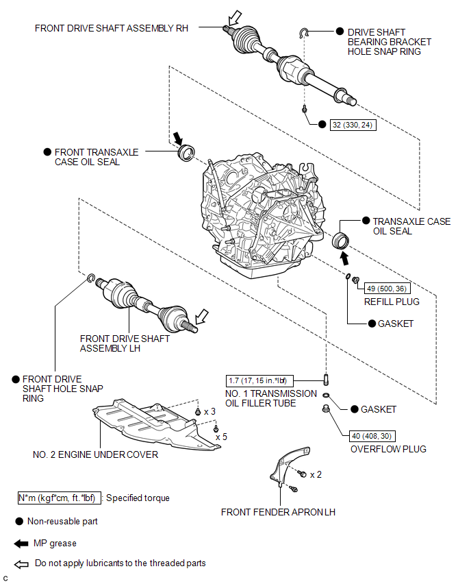
COMPONENTS
ILLUSTRATION
Replacement
REPLACEMENT
PROCEDURE
1. DRAIN AUTOMATIC TRANSAXLE FLUID
(a) Remove the No. 2 engine under cover and front fender apron LH.
|
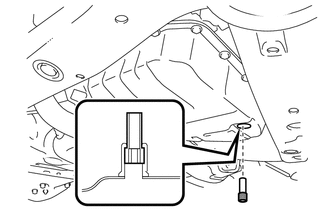
(b) Using a 6 mm socket hexagon wrench, remove the overflow plug and gasket from the automatic transaxle. |
|
.png)
|
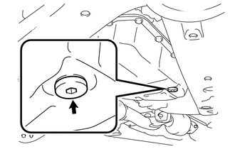
(c) Remove the refill plug and gasket from the automatic transaxle. |
|
.png)
|
(d) Using a 6 mm socket hexagon wrench, remove the No. 1 transmission oil filler tube from the automatic transaxle. |
|
(e) Drain automatic transaxle fluid from the automatic transaxle.
|
(f) Using a 6 mm socket hexagon wrench, install the No. 1 transmission oil filler tube to the automatic transaxle. Torque: 1.7 N┬Ęm {17 kgf┬Ęcm, 15 in┬Ęlbf} |
|
|
(g) Using a 6 mm socket hexagon wrench, install a new gasket and the overflow plug to the automatic transaxle. Torque: 40 N┬Ęm {408 kgf┬Ęcm, 30 ft┬Ęlbf} |
|
|
(h) Install a new gasket and the refill plug to the automatic transaxle. Torque: 49 N┬Ęm {500 kgf┬Ęcm, 36 ft┬Ęlbf} |
|
2. REMOVE FRONT DRIVE SHAFT ASSEMBLY
HINT:
See page .gif)
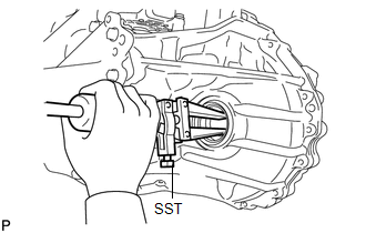
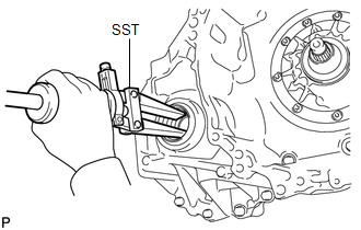
3. REMOVE TRANSAXLE CASE OIL SEAL
|
(a) Using SST, tap out the transaxle case oil seal. SST: 09308-00010 |
|
4. REMOVE FRONT TRANSAXLE CASE OIL SEAL
|
(a) Using SST, tap out the front transaxle case oil seal. SST: 09308-00010 |
|
5. INSTALL TRANSAXLE CASE OIL SEAL
|
(a) Using SST and a hammer, tap in a new transaxle case oil seal. SST: 09316-10010 SST: 09950-70010 09951-07100 Oil seal driven in depth: -0.5 to 0.5 mm (-0.0197 to 0.0197 in.) NOTICE: Check that the oil seal is installed in the correct direction. |
|
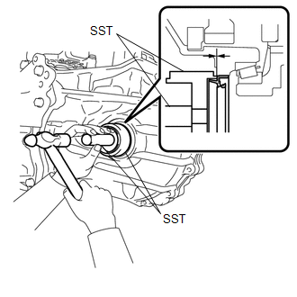
(b) Coat the lip of the transaxle case oil seal with MP grease.
6. INSTALL FRONT TRANSAXLE CASE OIL SEAL
|
(a) Using SST and a hammer, tap in a new front transaxle case oil seal. SST: 09316-60011 09316-00011 Oil seal driven in depth: -0.5 to 0.5 mm (-0.0197 to 0.0197 in.) NOTICE: Check that the oil seal is installed in the correct direction. |
|
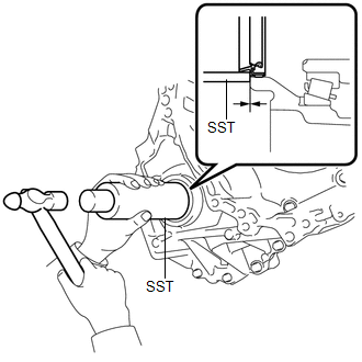
(b) Coat the lip of the front transaxle case oil seal with MP grease.
7. INSTALL FRONT DRIVE SHAFT ASSEMBLY
HINT:
See page
8. ADD AUTOMATIC TRANSAXLE FLUID
HINT:
See page
 Reassembly
REASSEMBLY
PROCEDURE
1. INSTALL FRONT DIFFERENTIAL CASE REAR TAPERED ROLLER BEARING
(a) Using SST and a press, install a new front differential case rear
tapered roller bearing (inne ...
 Oil Pump
...
Other materials about Toyota Venza:
Transmission Wire(when Using The Engine Support Bridge)
Components
COMPONENTS
ILLUSTRATION
Installation
INSTALLATION
PROCEDURE
1. INSTALL TRANSMISSION WIRE
(a) Coat the O-ring with ATF.
(b) Coat the bolt with ATF.
(c) Install the transmission ...
Fuel Receiver Gauge Malfunction
DESCRIPTION
The meter CPU uses the fuel sender gauge assembly to determine the level
of the fuel in the fuel tank. The resistance of the fuel sender gauge will
vary between approximately 7.5 ╬® with the float at the full position, and
185 ╬ ...
Inspection
INSPECTION
PROCEDURE
1. INSPECT VACUUM SWITCHING VALVE ASSEMBLY (for ACIS)
(a) Measure the resistance according to the value(s) in the table below.
Text in Illustration
*1
Body Ground
Stan ...

0.1566