Toyota Venza: Dtc Check / Clear
DTC CHECK / CLEAR
NOTICE:
When the diagnosis system is changed from normal mode to check mode or vice versa, all DTCs and freeze frame data recorded in normal mode are cleared. Before changing modes, always check and make a note of DTCs and freeze frame data.
HINT:
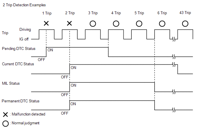
- DTCs which are stored in the ECM can be displayed on the Techstream. The Techstream can display the current, pending and permanent DTCs.
- If a malfunction is detected during the current driving cycle, current and permanent DTCs are stored.
- Some DTCs are not stored if the ECM does not detect the same malfunction again during a second consecutive driving cycle. However, such malfunctions, detected on only one occasion, are stored as pending DTCs.
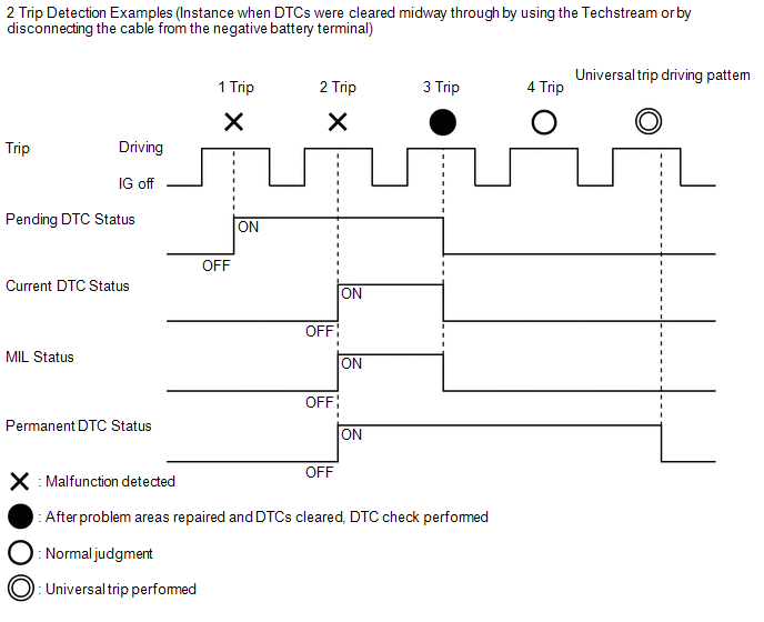
- Current and pending DTCs can be cleared by using the Techstream or by disconnecting the cable from the negative battery terminal. However, permanent DTCs cannot be cleared using either of these two methods.
- After clearing current DTCs using the Techstream (or by disconnecting the cable from the negative battery terminal), permanent DTCs can be cleared when the system is determined to be normal for the relevant DTCs and then the universal trip is performed. The driving pattern to obtain a normal judgment is described under the "CONFIRMATION DRIVING PATTERN" for the respective DTC.
|
Pending DTC |
Store condition |
Malfunction detected |
|
Clear condition |
System determined to be normal or DTCs cleared using Techstream or Cable disconnected from negative battery terminal |
|
|
Current DTC |
Store condition |
Malfunction detected (2nd trip) |
|
Clear condition |
No malfunctions in 40 driving cycles or DTCs cleared using Techstream or Cable disconnected from negative battery terminal |
|
|
Permanent DTC |
Store condition |
Malfunction detected (2nd trip) |
|
Clear condition |
Ignition switch turned to ON after normal judgment obtained in 3 consecutive driving cycles or After DTCs cleared using Techstream or cable disconnected from negative battery terminal, normal judgment obtained and universal trip performed (not for misfire and fuel system DTCs) or After DTCs cleared using Techstream or cable disconnected from negative battery terminal, malfunction not detected when universal trip driving performed (misfire and fuel system DTCs) |
|
|
MIL |
ON |
Malfunction detected (2nd trip) |
|
OFF |
Ignition switch turned to ON after normal judgment obtained in 3 consecutive driving cycles or DTCs cleared using Techstream or Cable disconnected from negative battery terminal |
HINT:
- Obtaining a normal judgment and performing a universal trip driving pattern can be done in the same driving cycle or in different driving cycles.
- It is unnecessary to obtain a normal judgment if the DTCs are misfire or fuel system DTCs.
1. CHECK DTC
(a) Connect the Techstream to the DLC3.
(b) Turn the ignition switch to ON.
(c) Turn the Techstream on.
(d) Enter the following menus: Powertrain / Engine / Trouble Codes.
(e) Check the DTC(s) and freeze frame data, and then write them down.
(f) Check the details of the DTC(s) (See page
.gif) ).
).
2. CLEAR DTC (Pending and Current DTC)
(a) Connect the Techstream to the DLC3.
(b) Turn the ignition switch to ON.
(c) Turn the Techstream on.
(d) Enter the following menus: Powertrain / Engine / Trouble Codes.
(e) Clear the DTCs.
3. CLEAR DTC (Pending and Current DTC without using Techstream)
(a) Perform either of the following operations:
(1) Disconnect the cable from the negative (-) battery terminal for more than 1 minute.
(2) Remove the EFI NO. 1 and ETCS fuses from the engine room relay block located inside the engine compartment for more than 1 minute.
4. CLEAR PERMANENT DTC
HINT:
Even if the following procedure is not performed, permanent DTCs are cleared by obtaining a normal judgment during 3 consecutive driving cycles.
(a) Connect the Techstream to the DLC3.
(b) Turn the ignition switch to ON.
(c) Turn the Techstream on.
(d) Enter the following menus: Powertrain / Engine / Trouble Codes.
(e) Check if permanent DTCs are stored.
HINT:
If permanent DTCs are not output, it is not necessary to continue this procedure.
(f) Clear the DTCs.
(g) Perform the respective confirmation driving patterns in order to obtain a normal judgment for the output DTCs.
HINT:
- Confirmation driving patterns do not need to be performed for misfire and fuel system DTCs.
- For the confirmation driving pattern, refer to the procedures for the
relevant DTC (See page ).
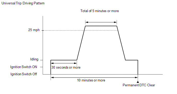
(h) Perform the universal trip.
HINT:
The driving pattern to obtain a normal judgment and the universal trip driving can be performed consecutively in the same driving cycle.
- Idle the engine for 30 seconds or more.
- Drive the vehicle at 40 km/h (25 mph) or more for a total of 5 minutes
or more.
HINT:
It is possible to complete the drive pattern even if the vehicle decelerates to less than 40 km/h (25 mph) during the driving cycle provided that the vehicle is driven at 40 km/h (25 mph) or more for a total of 5 minutes.
- Allow 10 minutes or more to elapse from the time the engine is started.
(i) Enter the following menus: Powertrain / Engine / Trouble Codes.
(j) Check that the permanent DTCs have been cleared.
HINT:
The permanent DTCs are cleared when the universal trip is completed.
 Diagnosis System
DIAGNOSIS SYSTEM
1. DESCRIPTION
When troubleshooting OBD II (On-Board Diagnostics) vehicles, an OBD
II scan tool (complying with SAE J1987) must be connected to the DLC3 (Data
Link Co ...
 Check Mode Procedure
CHECK MODE PROCEDURE
HINT:
Techstream only:
Compared to normal mode, check mode is more sensitive to malfunctions. Therefore,
check mode can detect malfunctions that cannot be detected in normal ...
Other materials about Toyota Venza:
Amplifier Antenna
Components
COMPONENTS
ILLUSTRATION
Removal
REMOVAL
PROCEDURE
1. REMOVE BACK DOOR PANEL TRIM ASSEMBLY
2. REMOVE AMPLIFIER ANTENNA ASSEMBLY
(a) Disconnect the 2 connectors.
(b) Remove th ...
Components
COMPONENTS
ILLUSTRATION
ILLUSTRATION
ILLUSTRATION
ILLUSTRATION
ILLUSTRATION
ILLUSTRATION
ILLUSTRATION
ILLUSTRATION
...
Air Conditioning Amplifier Communication Stop Mode
DESCRIPTION
Detection Item
Symptom
Trouble Area
Air Conditioning Amplifier Communication Stop Mode
"Air Conditioner" is not displayed on "CAN Bus Check" screen
o ...

0.1573